


 Sell on Robu


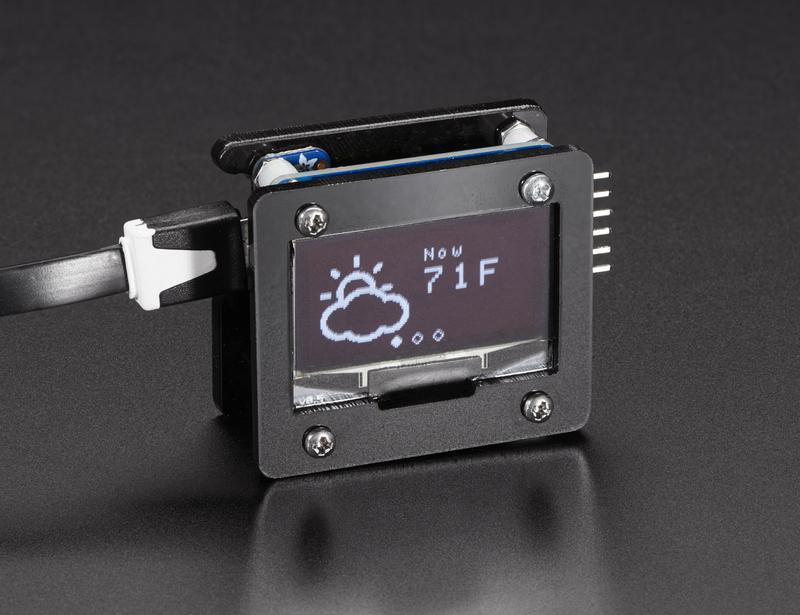
Hello Guys, today we are going to talk about the interfacing of OLED (organic LED) with NodeMCU. The very first sentence we print our Display window/ Serial monitor or any other LCD is "Hello World". So in this tutorial, we will gonna print "Hello world", later we will jump on displaying custom fonts and Custom image on OLED display.
[caption id="attachment_761001" align="aligncenter" width="296"]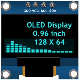 OLED display[/caption]
Step 1: Topics We Will Cover Today
- What is an OLED display?
- A detailed look at its module.
- Installing libraries for OLED
- Make OLED connection with NodeMCU
- Displaying Image and the objects on Display.
- Pros & Cons
- Common Errors have been done while programming and interfacing.
Today, We are going to see the above basic elements About OLED display, like:
- what is an OLED display?
- what are the size and dimensions OLED display have?
- Its hardware interface and library installation
- Displaying Custom images and objects/text on OLED
- what are the advantages and disadvantages of OLED?
- what care we do not take while handling with our OLED.
So, lets get started,
Step 2: Hardware Requirement.
We will need the following hardware requirement,
- A 0.96" (128x64) I2C OLED displays
- NodeMCu
- A breadboard
- Few jumper cables
- USB "type B" cable.
Step 3: What is an OLED Display?
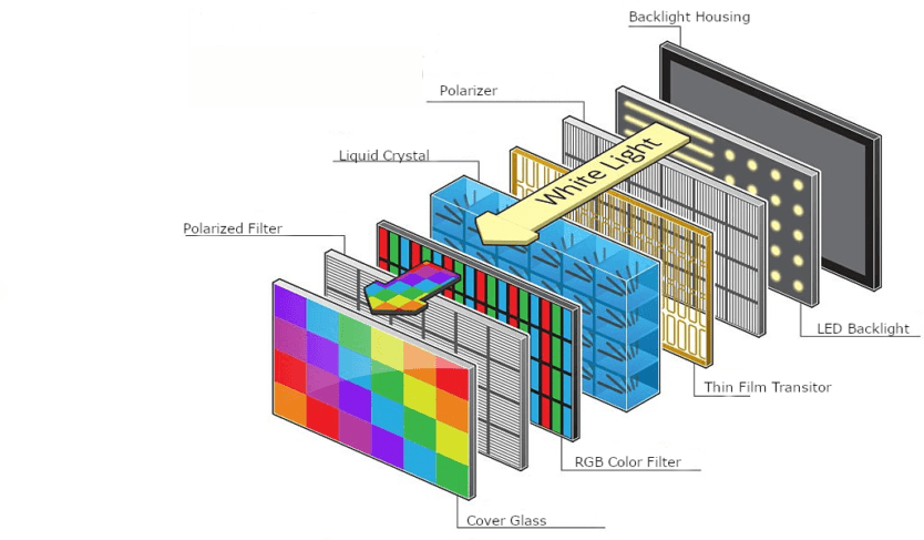
OLED (Organic Light-Emitting Diodes) is a flat light emitting technology, made by placing a series of organic thin films between two conductors. When an electrical current is applied, a bright light is emitted. OLEDs are emissive displays that do not require a backlight and so are thinner and more efficient than LCDs (which do require a white backlight).
[caption id="attachment_759720" align="aligncenter" width="422"]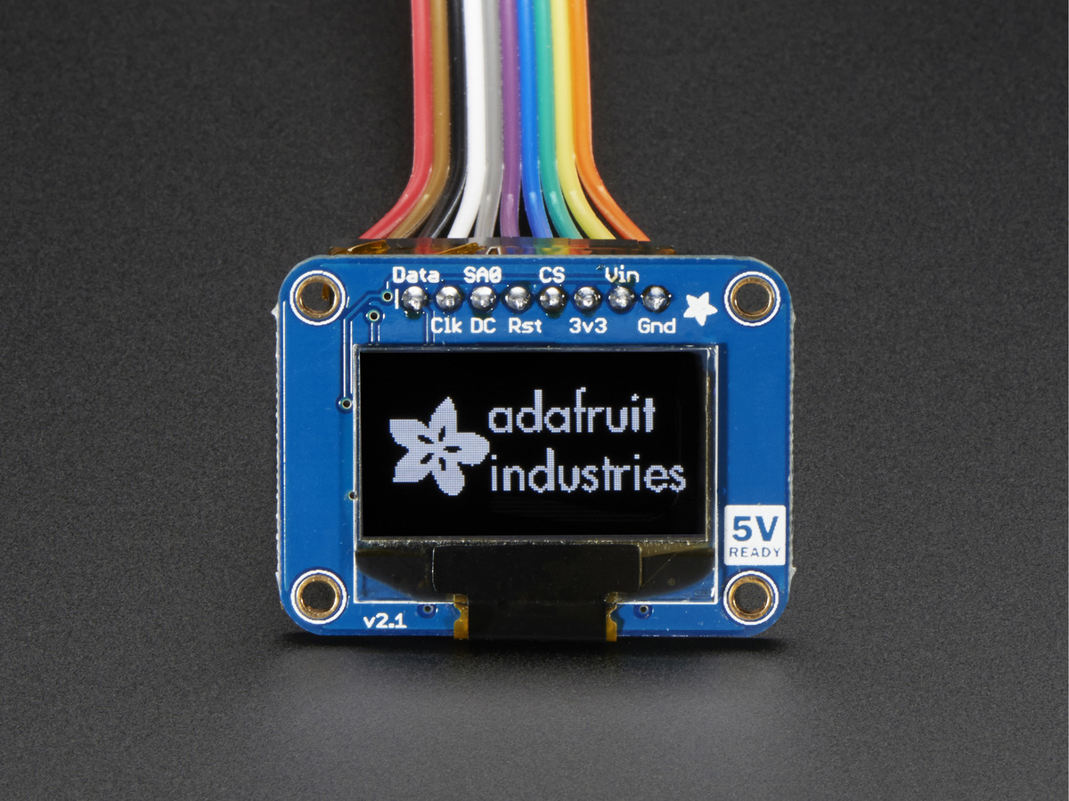 OLED[/caption]
As the display makes its light, no backlight is required. This significantly reduces the power required to run the OLED and is why the display has such high contrast, extremely wide viewing angle, and can display deep black levels.
So What's Organic About OLEDs?
OLEDs are organic because they are made from carbon and hydrogen. There's no connection to organic food or farming - although OLEDs are very efficient and do not contain any bad metals - so it's a real green technology.
How Do OLEDs Work?
An OLED is made by placing a series of organic thin films between two conductors. When an electrical current is applied, a bright light is emitted. Click here for a more detailed view of the OLED technology.
There are many OLED's in the market categorized on their:
- Sizes
- Color
- Brands
- Protocol
- SPI (Serial Peripheral Interface) or I2C
- Passive-matrix (PMOLED) or active-matrix (AMOLED) control scheme.
Step 4: Detailed Look
OLED I2C module has 4 pins which are VCC, GND, SCK, SDA. The backside of the OLED module has lots of SMD components of resistor and capacitors. The wiring of the OLED display is pretty simple. connect VCC and GND to VCC and GND of NodeMCU and SCK pin to D1 pin of NodeMCU, SDA pin on D2 pin of NodeMCU. The data connection is I2C (I²C, IIC, or Inter-Integrated Circuit) and this interface is also called TWI (Two Wire Interface).
[caption id="attachment_759718" align="aligncenter" width="471"]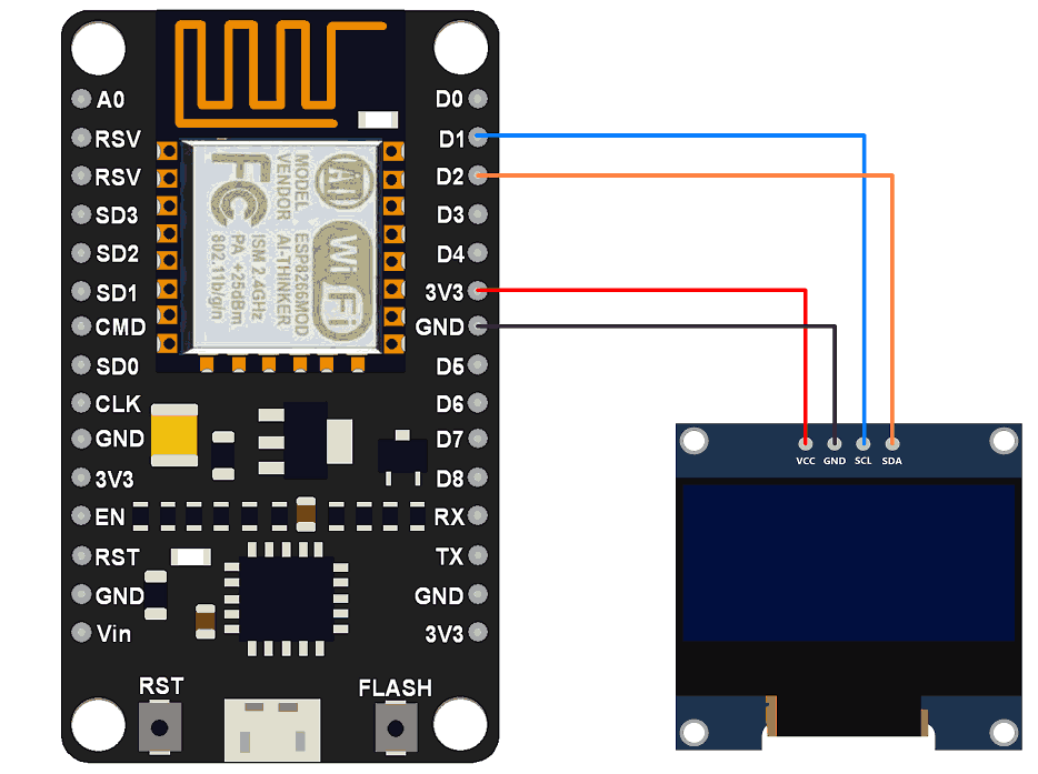 Interfacing OLED with NodeMCU[/caption]
Following things you can take on a note that:
- The on-board pins can be in a different order, so always triple check before hooking it up to your project.
- The operation voltage is between 3v to 5v but, it is best to use the guidance from the manufacturer's datasheet.
Features:
- OLED Driver IC: SSD1306
- Resolution: 128 x 64
- Visual Angle: >160°
- Input Voltage: 3.3V ~ 6V
- Compatible I/O Level: 3.3V, 5V
- Mini Size: 2.7 x 2.8cm
- Only Need 2 I/O Port to Control
- Pixel Color: Blue
- Full Compatible with Arduino
- Working temperature: -30°C ~ 70°C
- Module volume ( generous ): 27.0 x 27.0 x 4.1mm
- Factory configured for SPI protocol (can be easily changed to IIC)
Step 5: Installing Library For OLED
There are several libraries available to control the OLED display with the ESP8266. In this tutorial we’ll use two Adafruit libraries: Adafruit_SSD1306 library and Adafruit_GFX library.
There are two methods by which you can instsll this two libraries,
Method 1
- Open your Arduino IDE and Go to the path : Sketch/ Include libraries/manage libraries
- Go to the "Library Manager" and search "adafruit_SSD1306" and "adafruit_gfx"
Then type this two libraries into searchbox , select latest version and hit install.
[caption id="attachment_759781" align="aligncenter" width="535"]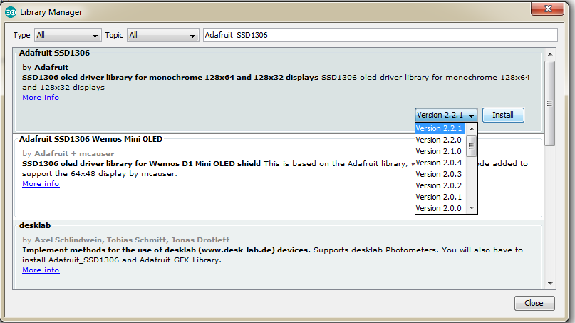 Installing Library[/caption]
Method 2
You can also download these two libraries, the downloading link I mention in 1st paragraph.
Once downloaded, copy the Adafruit_SSD1306-master folder from the downloaded zipped file into the Arduino libraries folder. This folder is usually found at Documents > Arduino > libraries on Windows systems. On Linux, it is usually found in the home folder > Arduino > libraries.
Step 6: Code
Now Go to File/example /Adafruit_SSD1306/ssd1306_128x64_i2c
[caption id="attachment_881584" align="aligncenter" width="493"]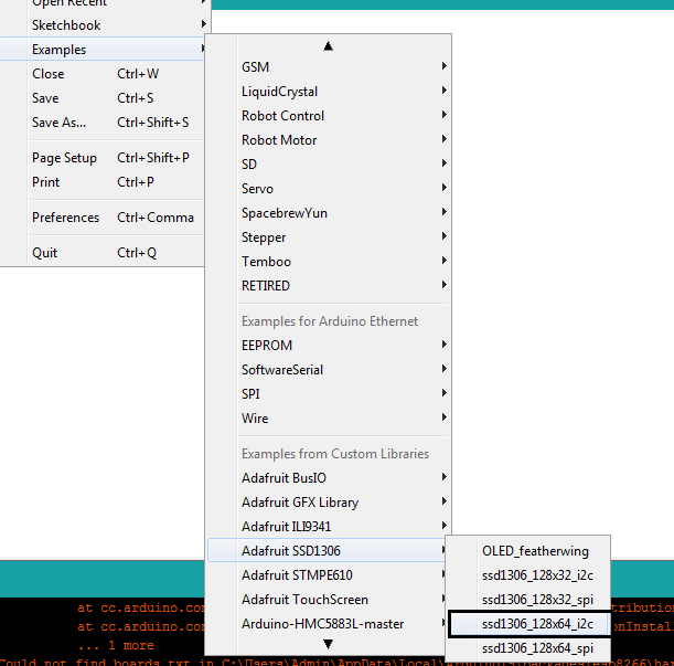 Path[/caption]
#define SCREEN_HEIGHT 64 // OLED display height, in pixels
If you are gonna use here, for 128x32 display you have to write there 32 instead of 64 , As we are using 128x64 OLED display, we will keep it as a 64
and in line,
#define OLED_RESET 4 // Reset pin # (or -1 if sharing Arduino reset pin)
Write LED_BUILEDIN instead of 4 for programming OLED with NodeMCU like this:
#define OLED_RESET LED_BUILETIN // Reset pin
The program will look like this,
#include <SPI.h>
#include <Wire.h>
#include <Adafruit_GFX.h>
#include <Adafruit_SSD1306.h>

#define SCREEN_WIDTH 128 // OLED display width, in pixels
#define SCREEN_HEIGHT 64 // OLED display height, in pixels

// Declaration for an SSD1306 display connected to I2C (SDA, SCL pins)
#define OLED_RESET    LED_BUILTIN // Reset pin # (or -1 if sharing Arduino reset pin)
Adafruit_SSD1306 display(SCREEN_WIDTH, SCREEN_HEIGHT, &Wire, OLED_RESET);

#define NUMFLAKES     10 // Number of snowflakes in the animation example

#define LOGO_HEIGHT   16
#define LOGO_WIDTH    16
static const unsigned char PROGMEM logo_bmp[] =
{ B00000000, B11000000,
  B00000001, B11000000,
  B00000001, B11000000,
  B00000011, B11100000,
  B11110011, B11100000,
  B11111110, B11111000,
  B01111110, B11111111,
  B00110011, B10011111,
  B00011111, B11111100,
  B00001101, B01110000,
  B00011011, B10100000,
  B00111111, B11100000,
  B00111111, B11110000,
  B01111100, B11110000,
  B01110000, B01110000,
  B00000000, B00110000 };

void setup() {
  Serial.begin(9600);

  // SSD1306_SWITCHCAPVCC = generate display voltage from 3.3V internally
  if(!display.begin(SSD1306_SWITCHCAPVCC, 0x3D)) { // Address 0x3D for 128x64
    Serial.println(F("SSD1306 allocation failed"));
    for(;;); // Don't proceed, loop forever
  }

  // Show initial display buffer contents on the screen --
  // the library initializes this with an Adafruit splash screen.
  display.display();
  delay(2000); // Pause for 2 seconds

  // Clear the buffer
  display.clearDisplay();

  // Draw a single pixel in white
  display.drawPixel(10, 10, SSD1306_WHITE);

  // Show the display buffer on the screen. You MUST call display() after
  // drawing commands to make them visible on screen!
  display.display();
  delay(2000);

  // display.display(). These examples demonstrate both approaches...


  testdrawchar();      // Draw characters of the default font

  testdrawstyles();    // Draw 'stylized' characters

  testdrawbitmap();    // Draw a small bitmap image

  // Invert and restore display, pausing in-between
  display.invertDisplay(true);
  delay(1000);
  display.invertDisplay(false);
  delay(1000);

  testanimate(logo_bmp, LOGO_WIDTH, LOGO_HEIGHT); // Animate bitmaps
}

void loop()
{
}

void testdrawchar(void) {
  display.clearDisplay();

  display.setTextSize(1);      // Normal 1:1 pixel scale
  display.setTextColor(SSD1306_WHITE); // Draw white text
  display.setCursor(0, 0);     // Start at top-left corner
  display.cp437(true);         // Use full 256 char 'Code Page 437' font

  // Not all the characters will fit on the display. This is normal.
  // Library will draw what it can and the rest will be clipped.
  for(int16_t i=0; i<256; i++) {
    if(i == '\n') display.write(' ');
    else          display.write(i);
  }

  display.display();
  delay(2000);
}

void testdrawstyles(void) {
  display.clearDisplay();

  display.setTextSize(1);             // Normal 1:1 pixel scale
  display.setTextColor(SSD1306_WHITE);        // Draw white text
  display.setCursor(0,0);             // Start at top-left corner
  display.println(F("Hello, world!"));

  display.setTextColor(SSD1306_BLACK, SSD1306_WHITE); // Draw 'inverse' text
  display.println(3.141592);

  display.setTextSize(2);             // Draw 2X-scale text
  display.setTextColor(SSD1306_WHITE);
  display.print(F("0x")); display.println(0xDEADBEEF, HEX);

  display.display();
  delay(2000);
}


void testdrawbitmap(void) {
  display.clearDisplay();

  display.drawBitmap(
    (display.width()  - LOGO_WIDTH ) / 2,
    (display.height() - LOGO_HEIGHT) / 2,
    logo_bmp, LOGO_WIDTH, LOGO_HEIGHT, 1);
  display.display();
  delay(1000);
}

#define XPOS   0 // Indexes into the 'icons' array in function below
#define YPOS   1
#define DELTAY 2

void testanimate(const uint8_t *bitmap, uint8_t w, uint8_t h) {
  int8_t f, icons[NUMFLAKES][3];

  // Initialize 'snowflake' positions
  for(f=0; f< NUMFLAKES; f++) {
    icons[f][XPOS]   = random(1 - LOGO_WIDTH, display.width());
    icons[f][YPOS]   = -LOGO_HEIGHT;
    icons[f][DELTAY] = random(1, 6);
    Serial.print(F("x: "));
    Serial.print(icons[f][XPOS], DEC);
    Serial.print(F(" y: "));
    Serial.print(icons[f][YPOS], DEC);
    Serial.print(F(" dy: "));
    Serial.println(icons[f][DELTAY], DEC);
  }

  for(;;) { // Loop forever...
    display.clearDisplay(); // Clear the display buffer

    // Draw each snowflake:
    for(f=0; f< NUMFLAKES; f++) {
      display.drawBitmap(icons[f][XPOS], icons[f][YPOS], bitmap, w, h, SSD1306_WHITE);
    }

    display.display(); // Show the display buffer on the screen
    delay(200);        // Pause for 1/10 second

    // Then update coordinates of each flake...
    for(f=0; f< NUMFLAKES; f++) {
      icons[f][YPOS] += icons[f][DELTAY];
      // If snowflake is off the bottom of the screen...
      if (icons[f][YPOS] >= display.height()) {
        // Reinitialize to a random position, just off the top
        icons[f][XPOS]   = random(1 - LOGO_WIDTH, display.width());
        icons[f][YPOS]   = -LOGO_HEIGHT;
        icons[f][DELTAY] = random(1, 6);
      }
    }
  }
}
The "#define OLED_RESET 4" > "#define OLED_RESET LED_BUILTIN" rest of the code is same as Arduino. I just skiped some functions, you can also keep the code as it is, its on your choice.
[caption id="attachment_868459" align="aligncenter" width="332"]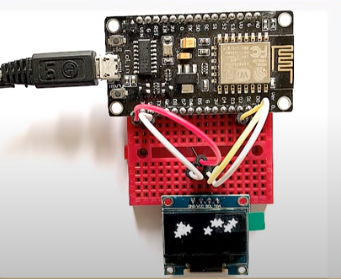 OLEDWithNodeMCU[/caption]
Step 7: Customizing Text & Adding Images
If you want to display more than a simple text, you can also display custom images on the OLED screen. For displaying such images and fonts you need to have good hands-on bit mapping. However, I m not that much good at that so I can also use the following websites to generate custom fonts:
http://oleddisplay.squix.ch/#/home
you just need to go to this website, select the size, fonts, family, Library Version as "Adafruit GFX Font" and then hit the "Create" button. On the right-hand side of this page, you can see how your font is going to look like on the actual display.
[caption id="attachment_870953" align="aligncenter" width="474"]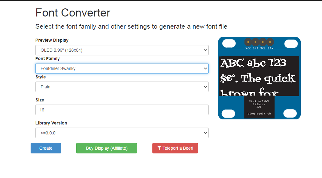 CustomFont[/caption]
Whatever data you select the webpage will generate a hex file so for copying that font file you need to create a new h file in the same folder of Arduino folder of Custom fonts, name it as "modified_font.h" in the same folder where your code is and copy and save the generated code into it. Then you just need to include the header file in your code to use the custom font.
#include "modified_font.h"
Then, you just need to set the font before displaying the text to apply the custom font to it.
display.setFont(&Your_Fonts_Name);
You can get the name of the font from the header file you just added to your project.
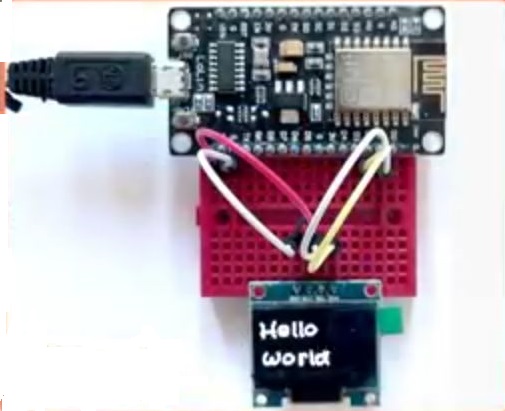 Hello World[/caption]
Displaying custom image
For displaying Bitmap Image, you need to create a 128x64 size image, you can pretty well do it by MS word, just go open that image by MS paint and change its pixel by 128x64 that's it, next is to upload that size of the image onto image converter website. link is given below :
http://javl.github.io/image2cpp/
[caption id="attachment_870984" align="aligncenter" width="483"]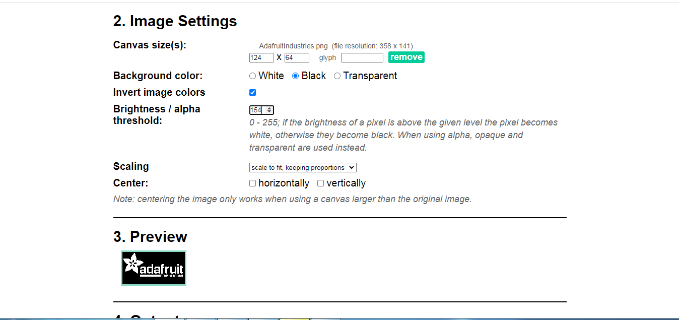 Adding Image[/caption]
[caption id="attachment_870987" align="aligncenter" width="488"]
Adding Image[/caption]
[caption id="attachment_870987" align="aligncenter" width="488"]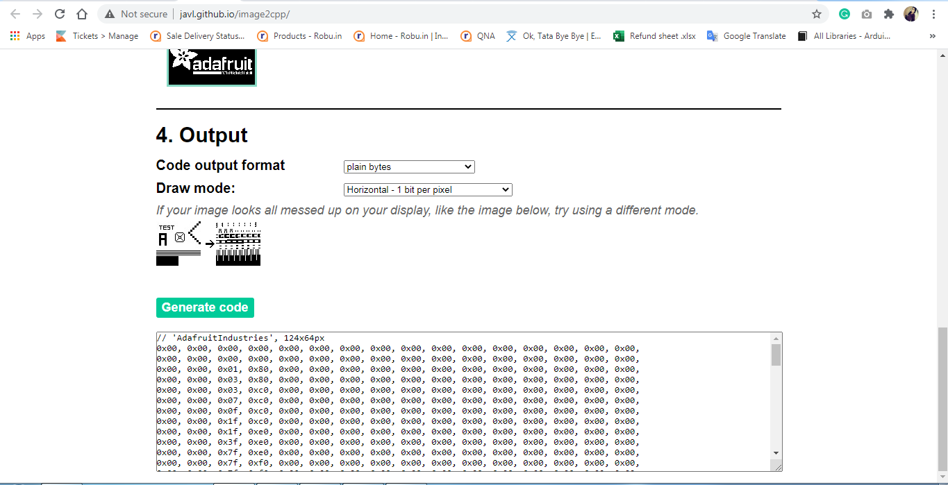 Image-code[/caption]
The website converts images into byte-strings, which can be used with Arduino and OLED displays. Upload the image to the website. Then put a check on the "Invert image colors" checkbox and change the "Output code format" to "Arduino Code" next select the orientation and hit the "Generate Code" button to generate the byte array. The "Preview" section shows you how your image will look like on the actual display.
[caption id="attachment_870991" align="aligncenter" width="229"]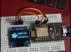 Custome_Image[/caption]
I have given both code of custom fonts and custom image, please download the zip file
Download code
Step 8: Advantages & Disadvantages
The appearance and the image of the OLED display are very attractive However it also has some disadvantages. OLED screens contain organic material, their lifespan is shorter than LCDs. Additionally, many OLED displays get burn-ins after showing the same image for a long time. After a burn-in, the image stays on the screen even after showing another image. So make sure you keep refreshing the screen every few seconds. Water can instantly damage the organic materials of these displays.
| Advantages | Disadvantages |
| Thin and lightweight display | Costly |
| Low power consumption | Short lifespan |
| No need for a backlight | Water damage |
| Deep black color | More likely to burn in |
| High Speed and Low response time | |
| Brightness and contrast are great | |
| Viewing angle are wider than LCD's |
Step 9: Common Errors

- Pick up the right library address in the header file and in your code #define SSD1306_I2C_ADDRESS 0x3C // in Adafruit_SSD1306.h and display.begin(SSD1306_SWITCHCAPVCC, 0x3C); // in your code
- If the address is wrong the OLED will not display anything
- while using NodeMCU make sure you replace the OLED_RESET from 4 to LED_BUILTIN #define OLED_RESET LED_BUILTIN
Step 10: Conclusion
In this last part, I want to conclude that OLED is a very beautiful display in order to display the image with Awesome features. But it has some disadvantages also like you can not play one image for a long time, it will burn the display, and due to organic matter, it is a little costly as compared to the normal LED display.
The Adafruit library and Image2cpp converter website make our work a lot easier to code, you just have to upload an image and add its file into your CPP file, and you are done.
So this is overall about OLED, you can print anything as per your imagination goes. Hope you like this post, if you find any doubt, please comment in the comment box.



Leave a Comment Your email address will not be published. Required fields are marked*