


 Sell on Robu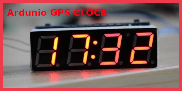


Hello and welcome to this tutorial, in this tutorial we are going to learn how to build an Arduino clock using UBlox NEO-M8M GPS Module. Speaking of time, you might be wondering why you need an external module to detect the running time if you’ve got an onboard timer in Arduino?
And the answer to this question is, yes, you can design your own clock using an internal timer, but this task will be more complicated. Therefore, using an external timer module to design an Arduino clock would be the best option.
Arduino Clock Using UBlox NEO-M8M GPS Module
You may have used the GPS module to design the tracking system but do you know that we can also use the GPS module to design the Arduino Clock? Yes, that’s right, the GPS module also sends time-related information and we’re going to use that information to design an Arduino GPS Clock.
Therefore, as you know UBlox NEO-M8M GPS Module gives a bunch of data in serial format, that data includes the exact position of the location. In addition to this GPS provides location coordinates (latitude and longitude) as well as time and date information. And to separate the required information from the data being sent by GPS, we are using an Arduino board.
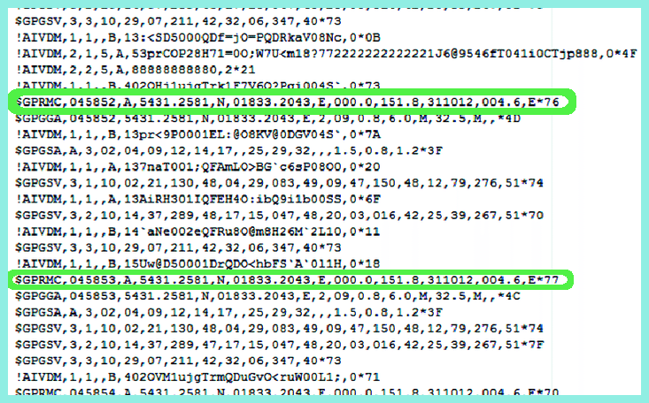
The output you are seeing in the above picture is NMEA format data received by UBlox NEO-M8M GPS module from various satellites. This output includes several lines, among these we need a line starting at $GPRMC. $GPRMC This term may be new to some of you, to understand this let us understand the format of the line starting with this word.
Watch the video for brief overview.
Code To Receive GPS Time From $GPRMC String
$GPRMC,182306,A,1523.82,N,00022.24,W,173.8,231.8,110120,004.2,W*70 In the above line, the letter next to $ GPRMC represents Coordinated Universal Time (UTC)) (“hhmmss.ss”).
Next, the letter next to the UTC number indicates the status of the data.
-
An ‘A’ indicates that you are getting a signal and things are working properly.
-
A ‘V’ means that your GPS is not connected to any satellite.
The two numbers after the letter “A” gives you your latitude and longitude.
The following table will help you understand the meaning of the above NMEA line.
|
Identifier |
Description |
|
220516 |
Time in hour minute seconds and milliseconds format.(h-m-s) 18-23-06 |
|
A |
Status // A= Active and V= No signal |
|
Latitude |
Latitude 15 deg. 23.82 min. North |
|
N |
Direction N=North, S=South |
|
Longitude |
Longitude(Co-ordinate) 22.24 min. West |
|
W |
Direction E= East, W=West |
|
Speed |
173.8 speed in knots |
|
Angle |
231.8 |
|
Date |
DATE in UTC – 11/01/20 |
|
MV |
Magnetic Variation |
|
W |
Direction of variation E/W |
|
|
|
I think this much information about the above NMEA string is sufficient to work on this project. If you want to know more about this format then please see this link.
Moving forward, you will need the following components to design the Arduino GPS Clock
Hardware Components
Software Components
Specification Of The UBlox NEO-M8M GPS Module
- Concurrent reception of up to 3 GNSS (GPS, Galileo, GLONASS, BeiDou).
- industry-leading–167 dBm navigation sensitivity.
- Security and integrity protection.
- Onboard ROM memory.
- Supports all satellite augmentation systems.
- Advanced jamming and spoofing detectionBackward compatible with NEO-7, NEO-6 and NEO-5 families.
Circuit Diagram
The Following image shows the circuit diagram of the Arduino GPS Clock.
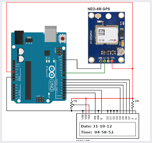
The image above shows the connection diagram, in this, we have connected the GPS module TX pin to the D9 pin of the Arduino Board and we are powering the GPS module through the Arduino itself.
Code For Arduino GPS Clock
#include<LiquidCrystal.h>
LiquidCrystal lcd(7, 6, 5, 4, 3, 2);

#include <SoftwareSerial.h>
SoftwareSerial Serial1(9, 10); // RX, TX

char str[70];
char *test="$GPRMC";
int temp,i;

void setup()
{
  lcd.begin(16,2);
  Serial1.begin(9600);
  lcd.setCursor(0,0);
  lcd.print("GPS Updated Clock");
  lcd.setCursor(0,1);
  lcd.print(" Circuit Digest ");
  delay(300);
}

void loop()
{
  serial1Event();
  if (temp)
  {
    lcd.clear();
    int str_lenth=i;
    int x=0,comma=0;
    String UTC_hour="";
    String UTC_minut="";
    String UTC_second="";
    String UTC_date="";
    String UTC_month="";
    String UTC_year="";
    String str1="";
    while(x<str_lenth)
    {
     if(str[x]==',')
     comma++;
      if(comma==1)
      {
        x++;
        UTC_hour+=str[x++];
        UTC_hour+=str[x++];
        UTC_minut+=str[x++];
        UTC_minut+=str[x++];
        UTC_second+=str[x++];
        UTC_second+=str[x];
        comma=2;
      }

      if(comma==10)
      {
        x++;
          UTC_date+=str[x++];
          UTC_date+=str[x++];
          UTC_month+=str[x++];
          UTC_month+=str[x++];
          UTC_year+=str[x++];
          UTC_year+=str[x];
      }
      x++;
    }

    int UTC_hourDec=UTC_hour.toInt();
    int UTC_minutDec=UTC_minut.toInt();
    int Second=UTC_second.toInt();
    int Date=UTC_date.toInt();
    int Month=UTC_month.toInt();
    int Year=UTC_year.toInt();

    int Hour=UTC_hourDec+5;
    if(Hour>23)
    {
     Hour-=24;
     Date+=1;
    }
    int Minut=UTC_minutDec+30;
    if(Minut>59)
    Minut-=60;


   // UTC_ind_zone_time
    lcd.clear();
    lcd.print("Date: ");
    lcd.print(Date);
    lcd.print("/");
    lcd.print(Month);
    lcd.print("/");
    lcd.print("20");
    lcd.print(Year);

     lcd.setCursor(0,1);
     lcd.print("Time: ");
     lcd.print(Hour);
    lcd.print(":");
    lcd.print(Minut);
    lcd.print(":");
    lcd.print(Second);
  //  delay(100);
    temp=0;
//    j=0;
    i=0;
    x=0;
    str_lenth=0;
//    k=0;
  }
 // delay(1000);
}

void serial1Event()
{
  while(1)
  {
   while (Serial1.available())            //checking serial data from GPS
   {
    char inChar = (char)Serial1.read();
     str[i]= inChar;                    //store data from GPS into str[]
     i++;
     if (i < 7)
     {
      if(str[i-1] != test[i-1])         //checking for $GPRMC sentence
      {
        i=0;
      }
     }
    if(i>65)
    {
     temp=1;
     break;
    }
  }
   if(temp)
    break;
  }
}
Conclusion
In this way, we have learned to design an Arduino clock using the GPS module. If there is any doubt, please let us know in the comment section. In our next blog, we will learn how to design an Arduino using the DS1307 RTC module.



Leave a Comment Your email address will not be published. Required fields are marked*