


 Sell on Robu


This article demonstrates the interfacing of the UBlox NEO-M8N global positioning system (GPS) module with Arduino Uno and Raspberry pi.
It is a very popular, cost-effective, high-performance GPS module. This GPS module comes with a ceramic patch antenna and an on-board memory chip, and a backup battery that is conveniently integrated with a broad range of microcontrollers.
GPS Interfacing with Arduino Uno:
We are using the U-Blox NEO-M8N GPS module to interface with Arduino Uno microcontroller.
This GPS module has 4 pins that work on the RS232 serial protocol. The 4 pins are VCC, GND, TX, and RX. The module just spits nonstop NMEA data strings to the TX pin. NMEA stands for National Marine Electronics Association and is a standard text protocol shared from all GPS.
Check out the video on how the GPS Module is interfaced with Arduino and its real-time working.
In Arduino, we have assigned the TX pin to D3 and Rx pin to D4. As per the connection,
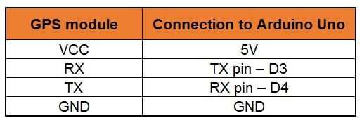
Connection diagram of the GPS Module with Arduino:

Download the libraries from the link below and install them in the Arduino IDE software.
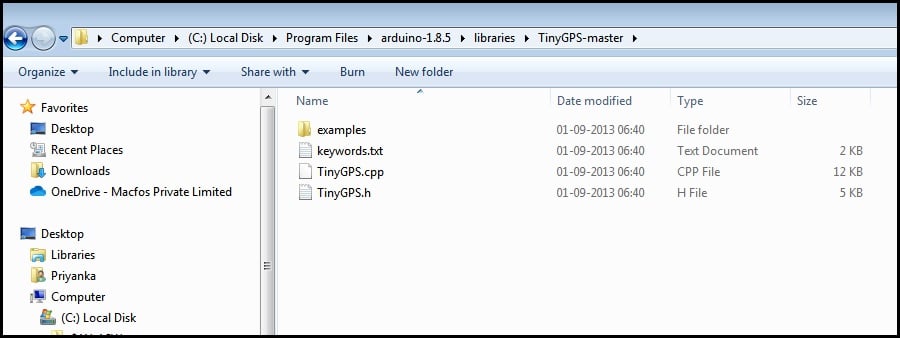
After installation of the library, open the Arduino IDE and open the example code below.
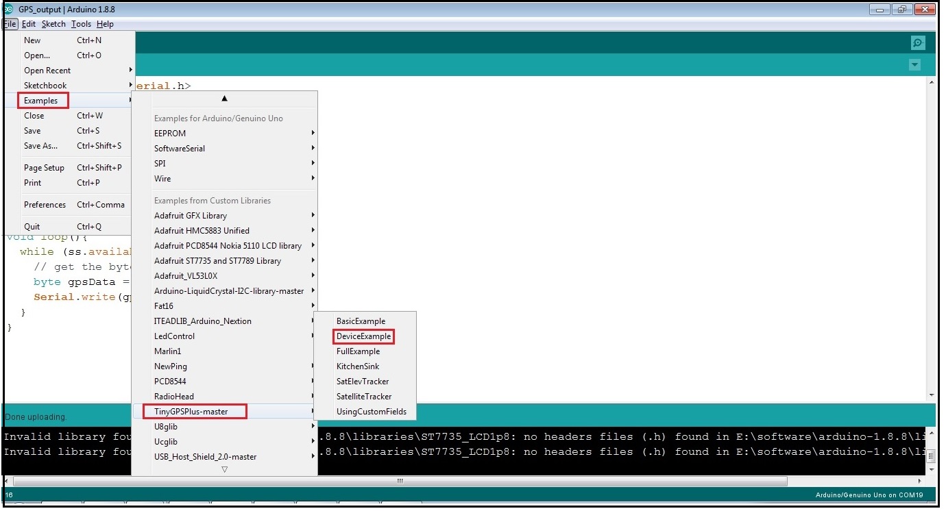
Or you can directly use the code below.
#include <SoftwareSerial.h>

static const int RXPin = 4, TXPin = 3;
static const uint32_t GPSBaud = 9600;

// The serial connection to the GPS device
SoftwareSerial ss(RXPin, TXPin);

void setup()
{
Serial.begin(115200);
ss.begin(GPSBaud);
}

void loop()
{

// Output raw GPS data to the serial monitor
while (ss.available() > 0){
Serial.write(ss.read());
}

}
The output can see on the serial window of Arduino IDE:
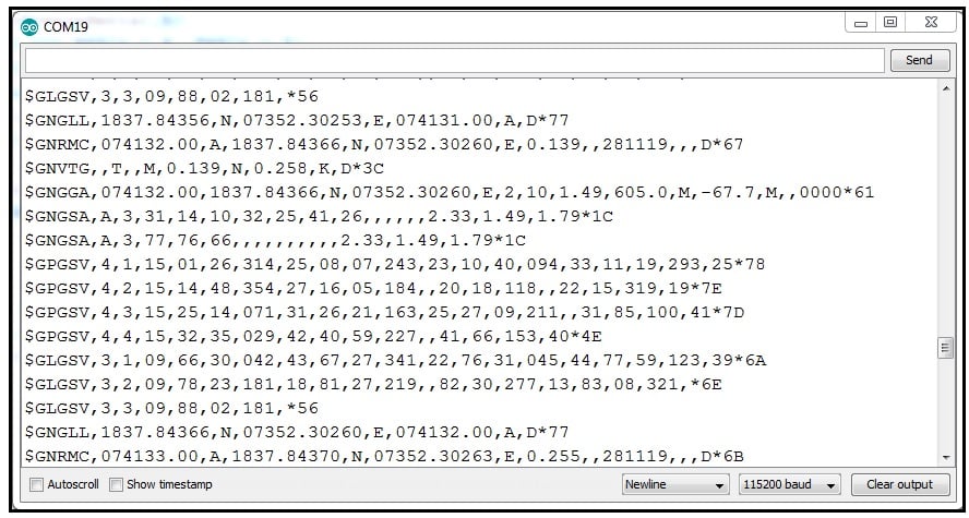
There are different types of NMEA sentences. The characters before the first comma indicate the type of message. The GN after the $ indicates a GPS position. The $GNGGA is the basic GPS NMEA message, it provides a 3D location and accurate data. In the following sentence:

- 073242– Represents the time at which the fix location was taken, 07:32:42 UTC
- 1837.84511,N– latitude 18 deg 37.84511’ N
- 07352.30436,E– Longitude 073 deg 52.30436′ E
- 1– fix quality (0 = invalid; 1= GPS fix; 2 = DGPS fix; 3 = PPS fix; 4 = Real-Time Kinematic; 5 = Float RTK; 6 = estimated (dead reckoning); 7 = Manual input mode; 8 = Simulation mode)
- 11– total number of satellites
- 17 – Horizontal dilution of position
- 8,M – Altitude, in meters above the sea level
- -67.7,M – Height of geoid (mean sea level) above WGS84 ellipsoid
- empty field – time in seconds since last DGPS update
- empty field – DGPS station ID number
- *60 – the checksum data, always begins with *
GPS Interfacing with Raspberry Pi:
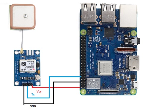
Let’s interface U-Blox NEO-M8N GPS module with Raspberry Pi to extract the GPS information. We are using Python code to interface the GPS module with Raspberry pi.
Connection diagram:
Download the Raspbian Operating system and install it in the memory card through Balena Etcher software.
Step 1: Setting up the UART in Raspberry Pi
sudo nano /boot/config.txt
At the bottom of the file, add the lines below,
dtparam=spi=on
dtoverlay=pi3-disable-bt
core_freq=250
enable_uart=1
force_turbo=1
Now, Press ctrl+x to exit and press y and enter to save.
Raspbian uses the UART as a serial console and so we need to turn off that functionality. To do so we need to change the /boot/cmdline.txt file. For safety before editing the file make a backup of that using the following command,
sudo cp boot/cmdline.txt boot/cmdline_backup.txt
sudo nano /boot.cmdline.txt
Replace the content with the line below,
dwc_otg.lpm_enable=0 console=tty1
root=/dev/mmcblk0p2 rootfstype=ext4 elevator=deadline fsck.repair=yes rootwait quiet splash plymouth.ignore-serial-consoles
Press Ctrl-X to exit, and press Y and enter to save.
Now reboot Pi to see the changes,
sudo reboot
Now, we will check how our GPS module is working.
Before checking this out, make sure that the yellow LED in the Neo 8M is blinking. Basically, the blinking of the yellow LED means that the GPS module is receiving the data perfectly. When the Yellow LED is blinking, run the following command. There are two serial ports in the Raspberry Pi 3: serial0 and serial1. Here, we have used serial0 because it will point to GPIO pins 14 and 15. Now to see the connection of the port with serial0, use the command below,
ls -l /dev
Step 2: Disabling the Raspberry Pi Serial Getty Service
After that, there are two possible outputs:
a. If in your output, Serial0 is linked with ttyAMA0, then to disable it, use the command below;
sudo systemctl stop [email protected]
sudo systemctl disable [email protected]
b. If in your output Serial0 is linked with ttys0, then to disable it use the below command,
sudo systemctl stop [email protected]
sudo systemctl disable [email protected]
Now, again, reboot the system using sudo reboot.
Step 3: Activating ttys0
In our system, we have disabled the ttyAMA0, the next thing is for us to enable the ttyso.
sudo systemctl enable [email protected]
Step 4: Install Minicom and pynmea2
Use the minicom Python library to connect with the GPS module and make sense of the data.
sudo apt-get install minicom
Use the pynmea2 Python library to parse the received NMEA data.
sudo pip install pynmea2
Step 5: Testing output
To test the GPS run the below command. The below data shows the data communication between the GPS Module and Raspberry pi microcontroller.
sudo cat /dev/ttyAMA0

Now, finally, we will write the python code for interfacing of the GPS module with Raspberry pi.
import serial
import time
import string import pynmea2
while True:      port=“/dev/ttyAMAO”
ser=serial.Serial(port, baudrate=9600, timeout=0.5)
dataout =pynmea2.NMEAStreamReader()
newdata=ser.readline()
if newdata[0:6] == “$GPRMC”:
newmsg=pynmea2.parse(newdata)
lat=newmsg.latitude
lng=newmsg.longitude
gps = “Latitude=” + str(lat) + “and Longitude=” +str(lng)
print(gps)
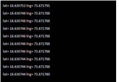
And here is the final output. it provides the data of your exact position in terms of Latitude and Longitude.
Conclusion
In Arduino and Raspberry pi interfacing, this GPS module provides the same location. I hope that you’ve found this article to be useful.
You can make a live GPS tracker using this GPS module, means we will be able to track this device from anywhere in the world, so stay tuned!




Samrat C
Tuesday, January 24, 2023