


 Sell on Robu


At places where water tanks are installed there is a need for making the tank filling process automatic as there will be no wastage of water. At some places there is a person operating the pump motor who just needs to get the indication that the tank is full or empty. At such places a IoT water level indicator is very useful as the water level can be viewed from anywhere using a smartphone application. In this blog we are going to give you step by step instructions such that you can build your own IoT water level indicator using nodeMCU and ultrasonic sensor HC-SR04.
As we are using ultrasonic sensor. Which uses ultrasound to detect the fluid level. The sensor doesn’t needs to be in contact with the fluid and that’s why It can be used for any fluid other than water like oil, chemicals and beverages.
In this project we are using the blynk IoT cloud platform. The fluid level can be viewed from smartphone using the blynk Iot application or from PC using blynk web dashboard. The circuit is easy to make. The main crux lies in getting the blynk platform to interact with nodeMCU. So let’s start with project.
Components required
- ESP8266 nodeMCU
- Ultrasonic sensor HC SR04
- Jumper wires (F to F) – 4 pcs
Circuit diagram
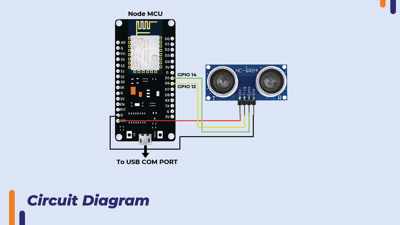
In the above circuit diagram the HC-SR04 module is connected to nodeMCU. The trigger pin is of HC-SR04 is connected to D6(GPIO12) and echo pin is connected to D5(GPIO14). The Vin pin outputs 5V as we are not connecting external 5V supply but taking from the USB com port of laptop. So Vin is connected to Vcc of HC-SR04 and GND is connected to GND of HC-SR04
About HC-SR04 ultrasonic sensor and it’s working?
The HC-SR04 ultrasonic sensor is popularly used in detection of obstacles and distance measurement. It has four pins, gnd, Echo, Trig and Vcc. The vcc and gnd pins are connected to the DC power source. Trig pin is used to trigger the ultrasound transmitter. Once the ultrasound is generated it is reflected back from the obstacle. The echo pin stays high for the time the sound is transmitted and received back by the receiver.
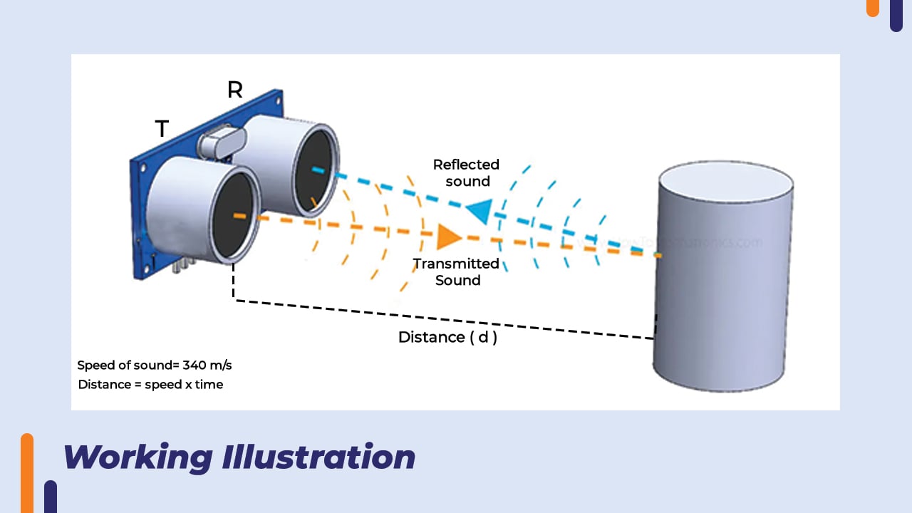
The working of this sensor is simple. The transmitter generates ultrasound when the trig pin is given a short pulse of 10 microseconds and at the same time the echo pin goes high. During this time the receiver is listening for ultrasound. The sound bounces from the obstacle and hits the receiver. The receiver picks up the ultrasound and the echo pin goes low. This means that the echo pin was high for the time the sound takes to go and come back.
As the speed of sound is 340m/s. The distance can be calculated using the formula.
Distance = Speed * Time.
As the time needs to be divided by 2 because it’s the total time sound takes to reach the object and bounce back. So the formula becomes.
Distance = Speed * Time/2
In this way this sensor can be used with a microcontroller and programmed accordingly to get the distance from the obstacle. In this project we are using a ESP8266 nodeMCU because we want to stream the water level on blynk cloud platform. So lets understand what is blynk and create a blynk account first.
What is Blynk?
Blynk is a mobile and web application platform that enables users to remotely control and monitor Internet of Things (IoT) devices. With Blynk, users can create custom apps for Android and iOS devices to interact with IoT hardware such as Arduino, Raspberry Pi, and ESP8266, among others. The platform offers a drag-and-drop interface to create a graphical user interface (GUI) for controlling and monitoring devices.
The platform also offers cloud services for storing data and facilitating communication between devices. Blynk is widely used by hobbyists and makers, as well as by professionals developing commercial IoT solutions.
Steps to create Blynk account
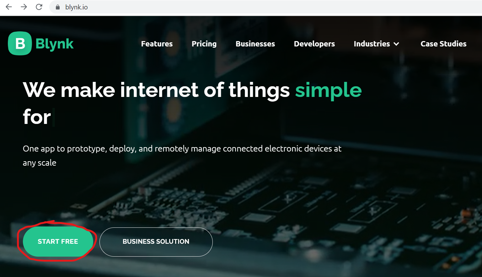
Step1 – Go to Blynk website and click on “start free”.
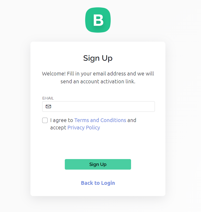
Step2 – Enter your email ID and tick the check box and click on “sign up”.
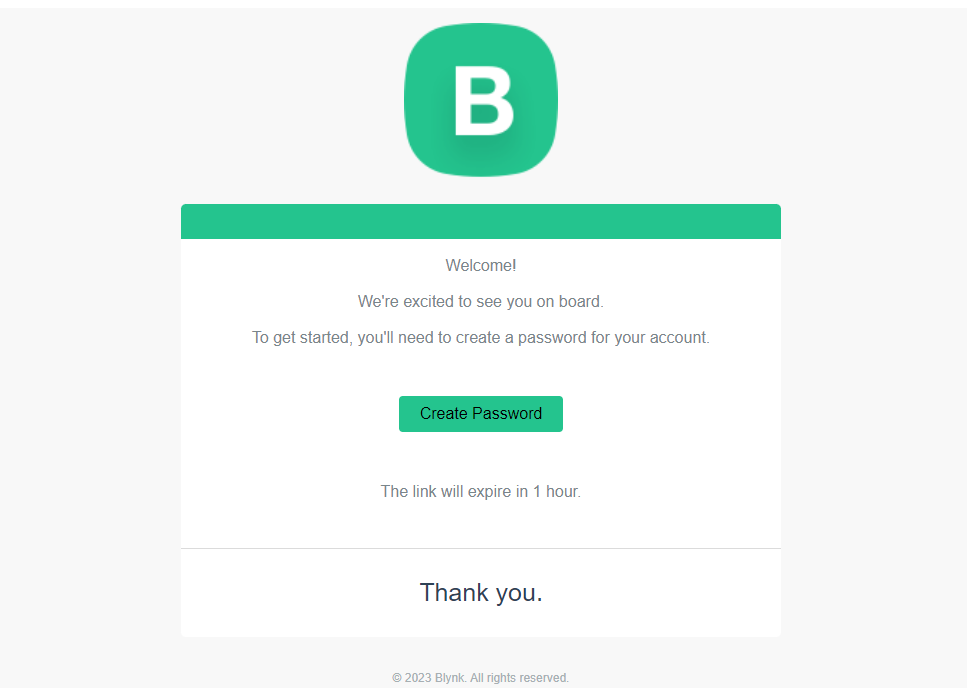
Step3 - You will receive an email by Blynk to create password. Click on “Create password”. Set a strong password and your account will be created.
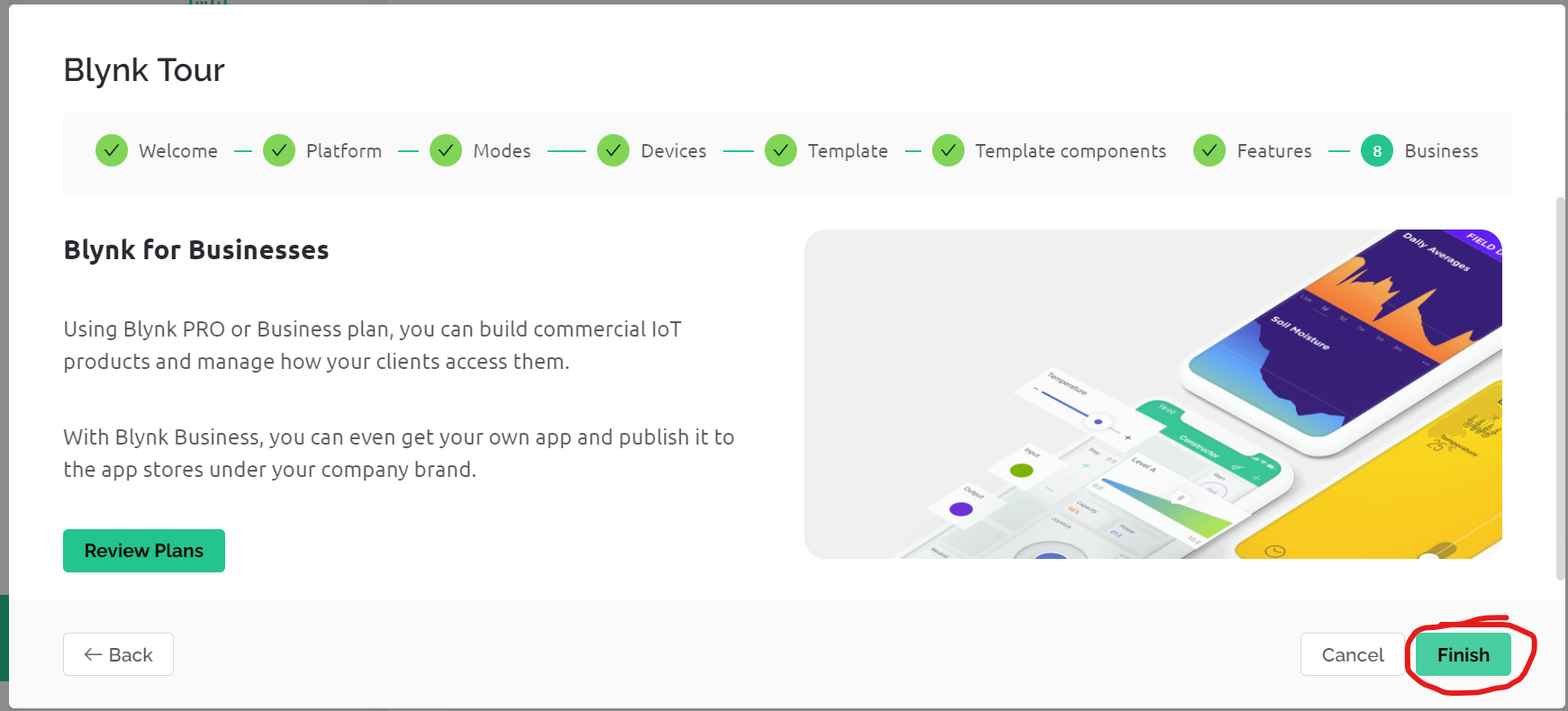
Step4 – Go through the blynk tour, read about blynk and and click on “Finish”
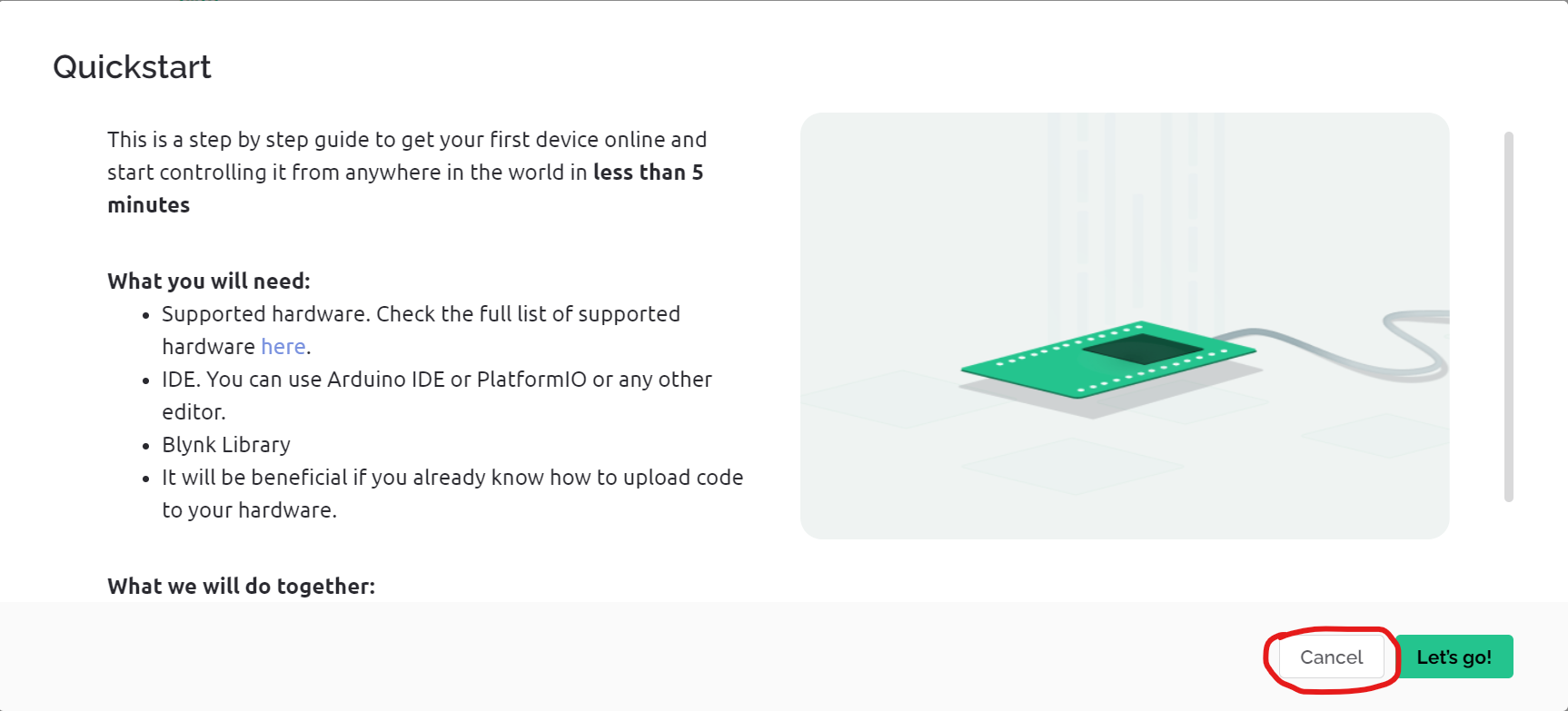
Step5 – Blink will ask you to create a Quickstart template. Click on “cancel”.
Step6 – Account is now created and you will see this page where all billing details are given.
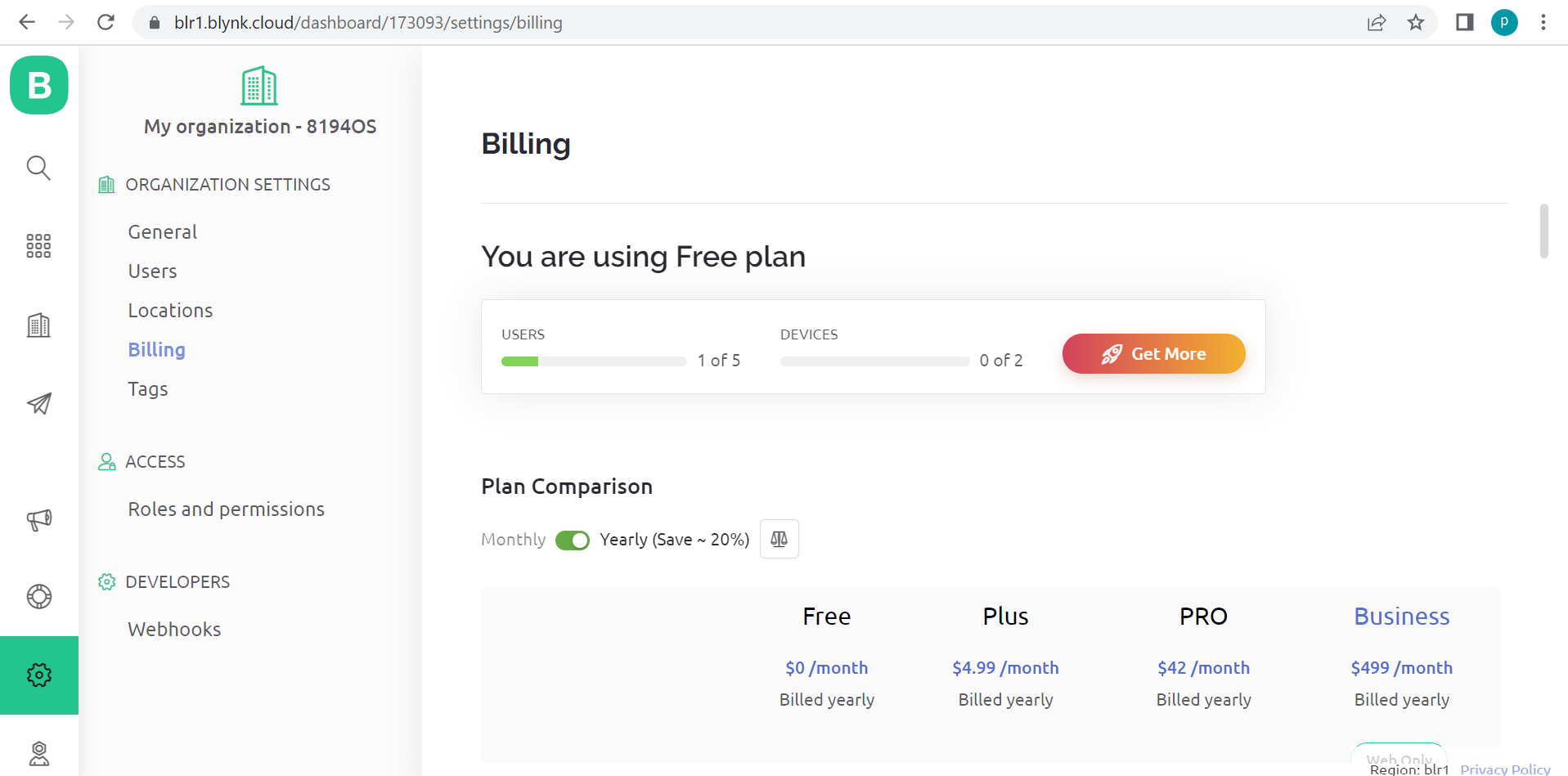
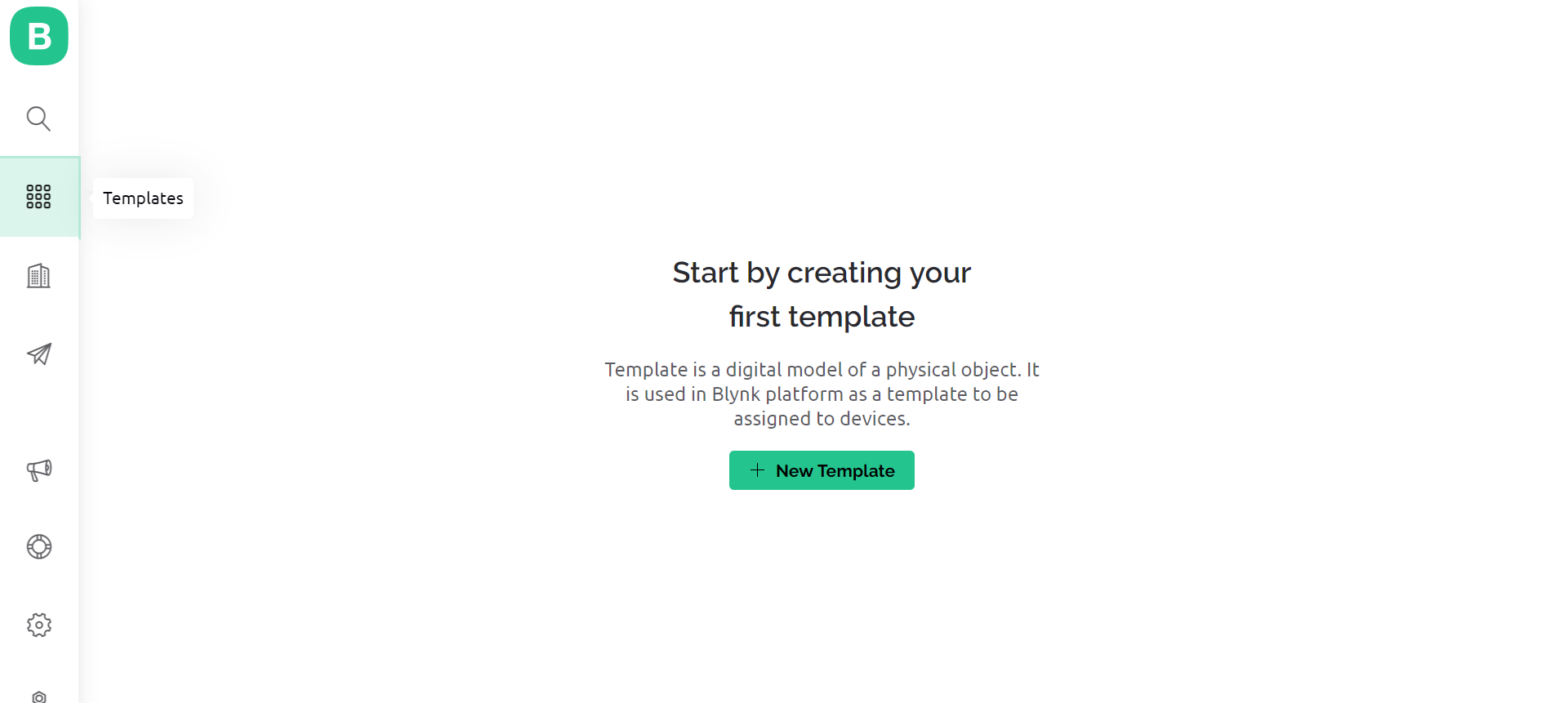
Steps for Creating a blynk template.
Now that the account is created let’s create blynk template
Step1- Go to “templates” and click on “New template”
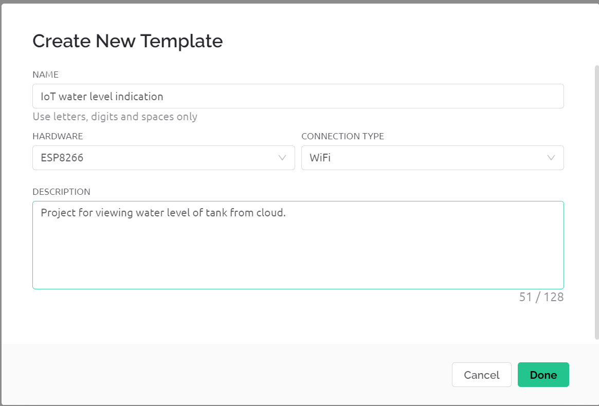
Step2- Give your template a name, select proper hardware board , connection type and description.
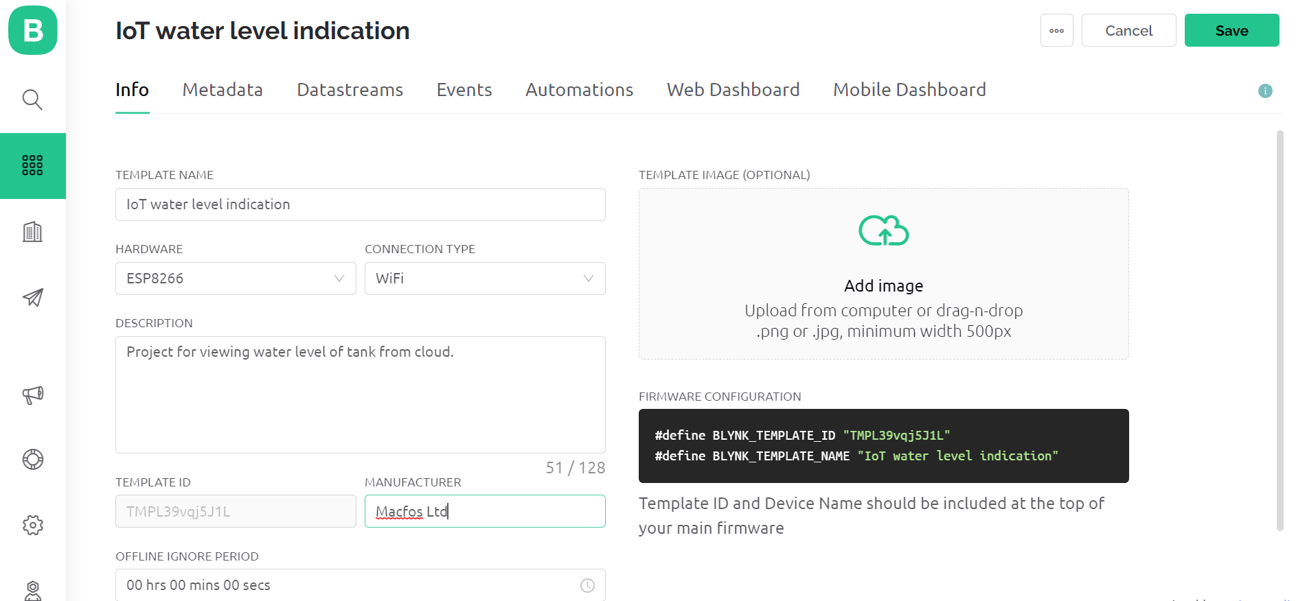
Step3 – Your template is now created. You will get “Template ID” and “Template name” under firmware configurations. Copy and save those credentials as it’s going to be used further in our code.
What is a datastream? Creating a datastream.
Datastream is a memory space given by Blynk on their server. It is to store our data which is received by the microcontroller pin and can be passed to a virtual pin datastream using blynk functions like “blynk.virtualWrite()”. A virtual pin is a type of datastream which can hold numerical data.
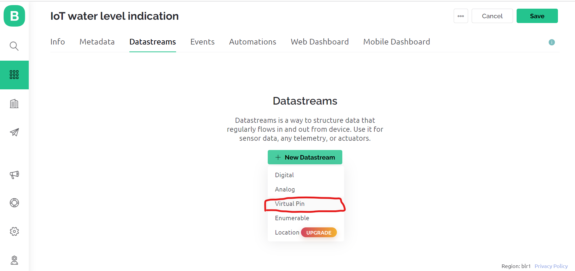
Step1 – Go to datastream and create a virtual pin datastream.
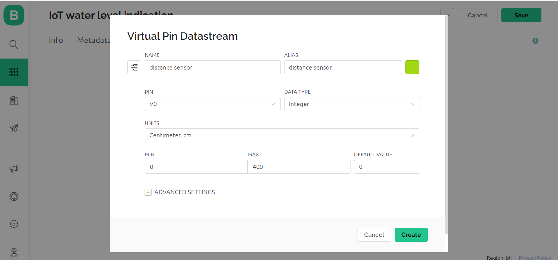
Step2- Give virtual pin a name, select proper datatype and range. As the HC-SR04 can measure only up to 400cm. I have given a range from 0 to 400cm. Also units is “centimetres”. Next, click on create. Datastream is now created.
Now we are ready for the Arduino IDE part. If it’s your first time with ESP module then go through this beginners guide blog. It will guide you on how to make ESP boards compatible with Arduino IDE.
Open the Arduino IDE.
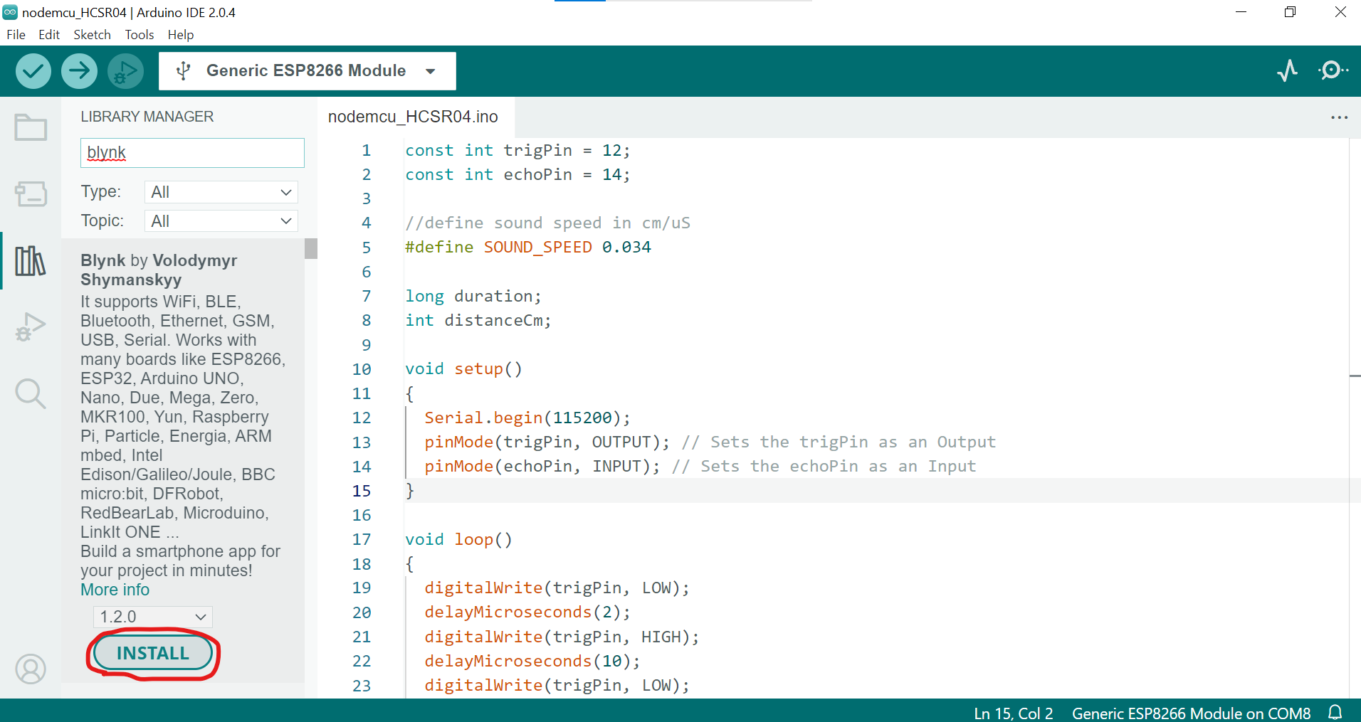
- Installing the blynk library.
Code
Upload the below given code
#define BLYNK_TEMPLATE_ID "Your id"
#define BLYNK_TEMPLATE_NAME "your name"
#define BLYNK_FIRMWARE_VERSION "0.1.0"
#define BLYNK_PRINT Serial
#define APP_DEBUG
#include "BlynkEdgent.h"
BlynkTimer timer;
const int trigPin = 12;
const int echoPin = 14;
//define sound speed in cm/uS
#define SOUND_SPEED 0.034
long duration;
int distanceCm;
void myTimer()
{
Blynk.virtualWrite(V0,distanceCm);
delay(1000);
}
void setup() {
Serial.begin(115200);
pinMode(trigPin, OUTPUT); // Sets the trigPin as an Output
pinMode(echoPin, INPUT);
delay(100);
timer.setInterval(1000L, myTimer);
BlynkEdgent.begin();
}
void loop() {
digitalWrite(trigPin, LOW);
delayMicroseconds(2);
digitalWrite(trigPin, HIGH);
delayMicroseconds(10);
digitalWrite(trigPin, LOW);
// Reads the echoPin, returns the sound wave travel time in microseconds
duration = pulseIn(echoPin, HIGH);
distanceCm = duration * SOUND_SPEED/2;
Serial.print("Distance (cm): ");
Serial.println(distanceCm);
delay(500);
BlynkEdgent.run();
timer.run();
}
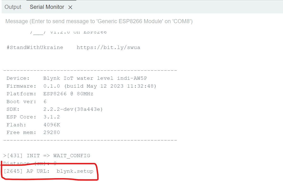
After the code is uploaded then open the serial monitor and reset the board. The name of “Blynk” will appear. At the end you should see the “AP URL: blynk.setup” this means you are ready for next step, that is to create the Blynk device.
Creating blynk device using the blynk mobile application.
Keep the nodeMCU connected to the com port of your pc or laptop and also keep the “Serial monitor” open so that you can see the status after each step is executed.
Step1 – Download the Blynk mobile app from the Google Play Store. Its also available on IOS.
Step2 – After downloading open the Blynk app and click on “Add New Device” >> “find nearby devices” >> start >> continue.
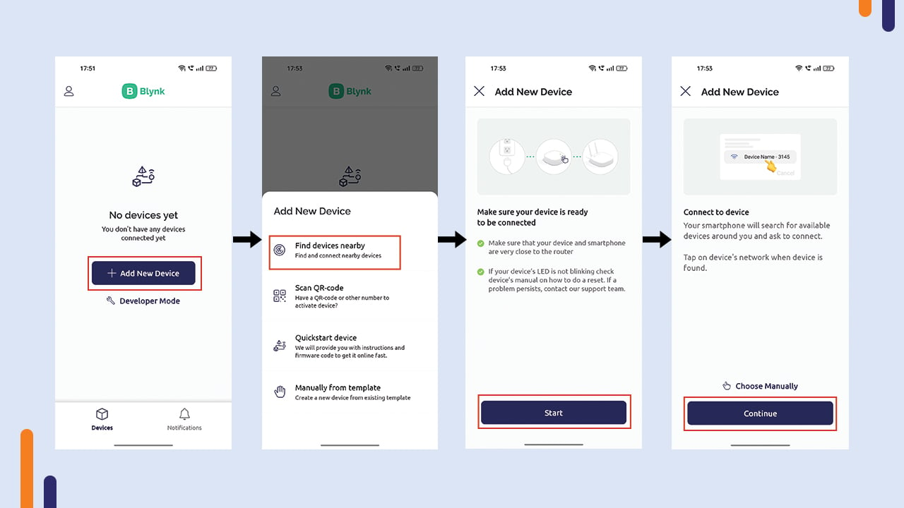
Wireless Settings >> Click on the ESP device Access point >> connect to the wifi network >> wait till device goes online.

After device is connected click on “finish”>> click on the settings icon >> add the “gauge” from the widget box from dashboard
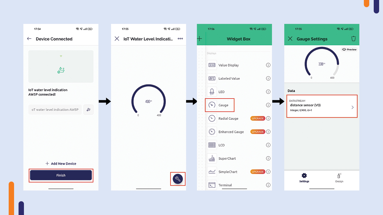
The device is now created along with the dashboard.
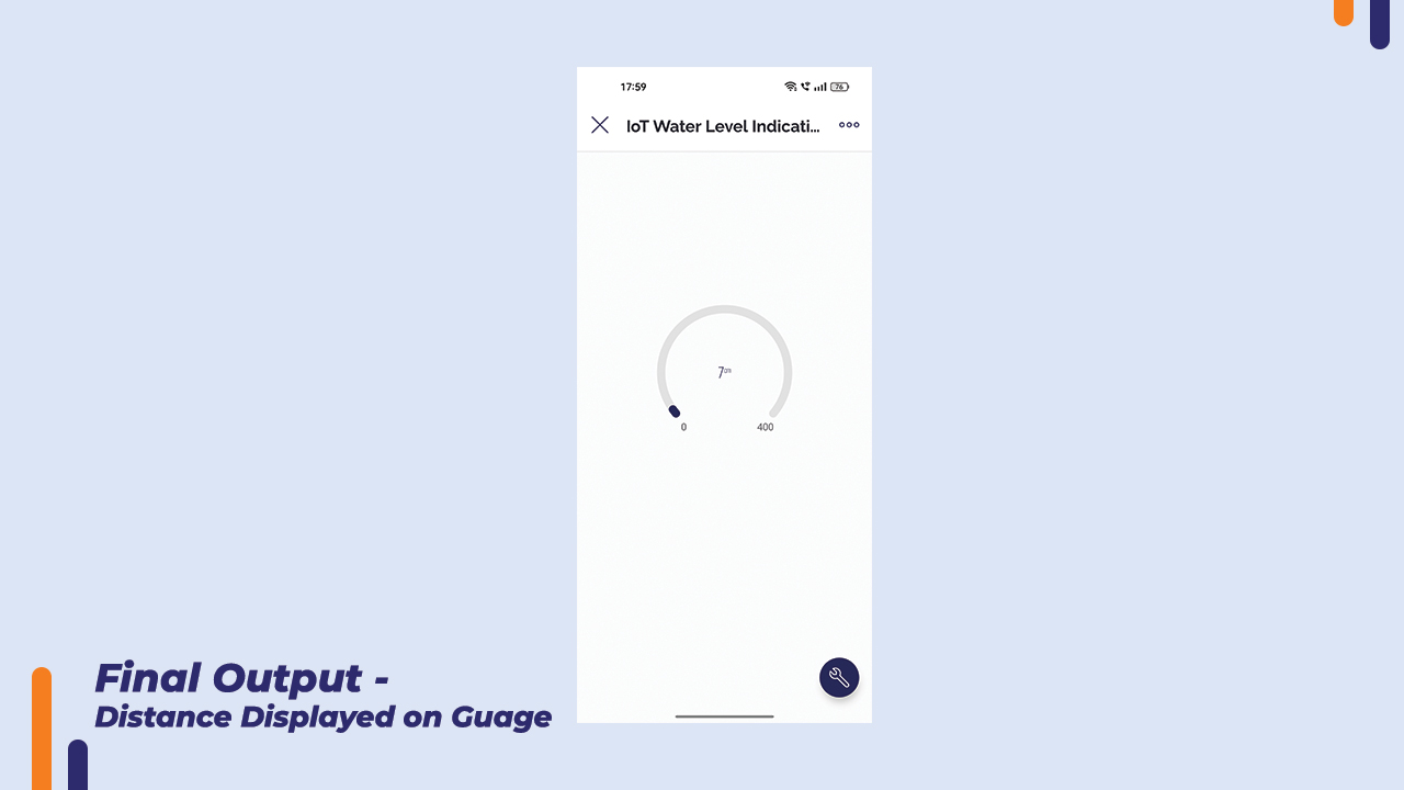
The changes we make on dashboard by using blynk app are also updated on the blynk web dashboard. The website and app both are linked. Now we can view water level from blynk app and also from blynk website.
Conclusion
In this way we created a IoT water level indicator using the blynk app. The water level can be viewed from a remote location. If you have any doubt regarding any part of this blog then feel free to comment it. Our team will be there to assist you.
Check out our YouTube channel for more interesting electronic project videos.





Leave a Comment Your email address will not be published. Required fields are marked*