


 Sell on Robu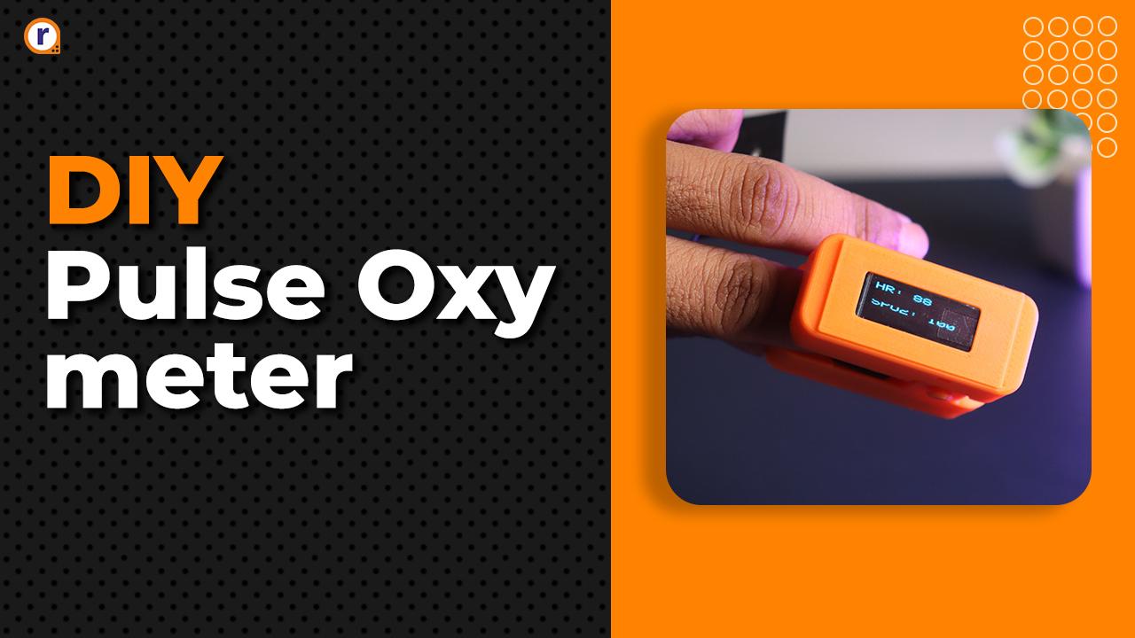


Built a smart pulse oximeter which measure's the heart rate and spo2 using MAX30102 sensor and Seeed Studio XIAO ESP32C3
What is Seeed Studio XIAO ESP32C3
For Internet of Things projects, Seeed Studio XIAO-ESP32C3 is a small development board. The Espressif ESP32-C3 chip powers it and provides Bluetooth and WiFi connectivity. With its robust floating-point unit and 32-bit RISC-V CPU, the ESP32-C3 offers effective arithmetic processing. The board ensures good radio frequency performance with IEEE 802.11 b/g/n WiFi and Bluetooth 5 (LE) compatibility.
For increased wireless signal strength, the XIAO-ESP32C3 has an external antenna and a compact, single-sided design. It has eleven digital I/O pins for PWM applications and four analog I/O pins for ADC. With its several interfaces (UART, I2C, and SPI), the board can be used for a wide range of applications. For simple programming and debugging, it also includes a reset button and a bootloader mode button.
Features of Seeed Studio XIAO ESP32C3
Features
Strong CPU: ESP32-C3, a 32-bit RISC-V single-core processor with a maximum frequency of 160 MHz
Entire wireless subsystem: Supports Station mode, SoftAP mode, SoftAP + Station mode, and promiscuous mode; complies with IEEE 802.11b/g/n protocol.
Subsystem for Bluetooth LE: supports Bluetooth mesh and Bluetooth 5 functionalities.
Extremely Low Power: Power usage during deep sleep is roughly 43μA.
Improved radio frequency performance: includes an external radio antenna
Chip for charging batteries: facilitates the charge and discharge control of lithium batteries
Rich on-chip resources: 4MB of on-board flash memory and 400KB of SRAM
incredibly tiny size: The size of a thumb (20 x 17.5 mm) The classic form-factor of the XIAO series is ideal for wearables and small projects.Features
Strong CPU: ESP32-C3, a 32-bit RISC-V single-core processor with a maximum frequency of 160 MHz
Entire wireless subsystem: meets the IEEE 802.11b/g/n protocol requirements.
Bluetooth LE subsystem: Facilitates Bluetooth mesh and Bluetooth 5 capabilities
Ultra-Low Power: The power used for deep sleep is approximately 43μA.
Improved radio frequency performance: includes an external radio antenna
Chip for charging batteries: facilitates the charge and discharge control of lithium batteries
Rich on-chip resources: 4MB of on-board flash memory and 400KB of SRAM
incredibly tiny size: The size of a thumb (20 x 17.5 mm) The classic form-factor of the XIAO series is ideal for wearables and small projects.
Hardware Requirement
- Seeed Studio XIAO ESP32C3
- MAX30102 Heart Rate and Pulse Oximeter Sensor
- 0.91 INCH OLED Display
- Jumper wires
- Breadboard
- 3D printed case
- Type C-Cable
Software requirement
- Arduino IDE
- Arduino cloud
- Arduino cloud Web
- Arduino IOT Remote App
- Arduino create agent for cloud
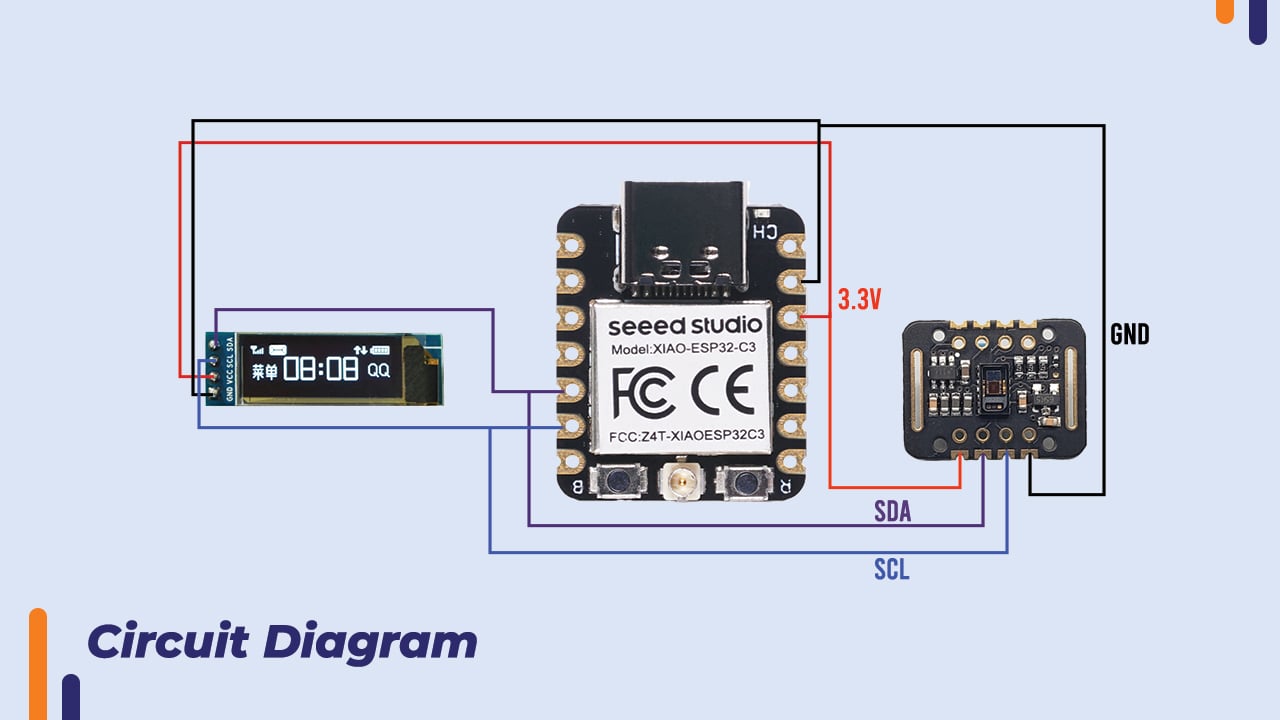
Circuit Diagram
Interface the components as per circuit diagram


Adding Compatible Board and Libraries
Files-> Preferences->ADD below URLs in Additional bord manager ->click OK
http://arduino.esp8266.com/stable/package_esp8266com_index.json
https://files.seeedstudio.com/arduino/package_seeeduino_boards_index.json
https://raw.githubusercontent.com/espressif/arduino-esp32/gh-pages/package_esp32_index.json

Arduino cloud interfacing
Follow the same procedure according to cloud irrigation blog
Link- https://robu.in/how-to-make-projectusing-arduino-nano-esp-32-arduino-cloud/
Create Thing
Configure network
Create a dashboard
Link variable
Open Sketch in full Editor
just Create float variable Heart rate and SPO2
Edit the code according to variables
Arduino Create Agent
Select the proper Board and port
Download Sketch from Arduino cloud sketch
Add network credential properly with device secret key.
(NOTE: Don’t forget to pause Arduino create agent else IDE can throw ERROR)
Libraries installation
Make sure these libraries are installed OakOLED, DFRobot_MAX30102, Adafruit_GFX, Adafruit_SSD1306
If not installed them or add them from library manager

Code
#include "arduino_secrets.h"
#include "thingProperties.h"
#include <Wire.h>
#include <OakOLED.h>
#include <DFRobot_MAX30102.h>
#include "Adafruit_GFX.h"
#include <Adafruit_SSD1306.h>

OakOLED oled;
DFRobot_MAX30102 particleSensor;

void setup() {
  Serial.begin(9600);
  delay(1500);

  initProperties();
  ArduinoCloud.begin(ArduinoIoTPreferredConnection);
  setDebugMessageLevel(2);
  ArduinoCloud.printDebugInfo();

  oled.begin();

  while (!particleSensor.begin()) {
    Serial.println("MAX30102 was not found");
    delay(1000);
  }

  particleSensor.sensorConfiguration(50, SAMPLEAVG_4, MODE_MULTILED, SAMPLERATE_100, PULSEWIDTH_411, ADCRANGE_16384);
}

void loop() {
  ArduinoCloud.update();

  int32_t SPO2;
  int8_t SPO2Valid;
  int32_t heartRate;
  int8_t heartRateValid;

  Serial.println(F("Wait about four seconds"));

  particleSensor.heartrateAndOxygenSaturation(&SPO2, &SPO2Valid, &heartRate, &heartRateValid);

  Serial.print(F("Heart Rate: "));
  Serial.print(heartRate, DEC);
  Serial.print(F(", Valid: "));
  Serial.print(heartRateValid, DEC);
  Serial.print(F("; SPO2: "));
  Serial.print(SPO2, DEC);
  Serial.print(F(", Valid: "));
  Serial.println(SPO2Valid, DEC);

  // Display results on OLED
  oled.clearDisplay();
  oled.setTextSize(2);
  oled.setTextColor(SSD1306_WHITE);
  oled.setCursor(0, 0);
  oled.print(F("HR: "));
  oled.print(heartRate);
  oled.setCursor(0, 40);
  oled.print(F("SPO2: "));
  oled.print(SPO2);
  oled.display();

  // Update Arduino IoT Cloud variables
  hR = heartRate;
  sPO2 = SPO2;

  delay(2000); // Adjust the delay as needed
}
Debugging and Uploading code
- Connect the circuit on breadboard as per circuit diagram.
- Verify and upload the above code into controller board.
- Make sure your Wi-Fi is on and proper credential is provided in the code.
- Check if Seeed Studio board Is connected to Wi-Fi/hotspot
- If connections and code are proper Pulse sensor will turn On with OLED display and after placing finger on sensor it will start showing Heart rate and oxygen.
- Just know that board is generic so read can some time will not piracies if you need precise reading you can you more precise sensor like DF robot max30102,sparkfumax30102.
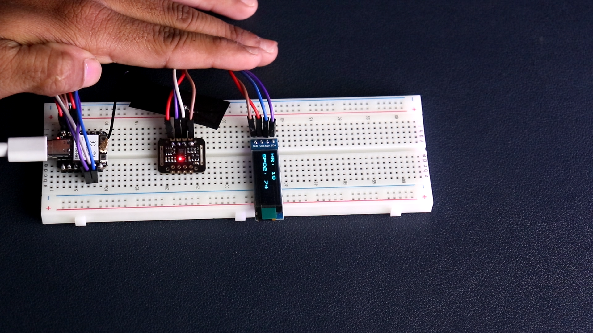
Breadboard test connections
Connections are made according to circuit diagram
- Make the connection on breadboard as per circuit diagram for testing and connect SEEED studio XIAO ESP32 C3 board with you PC or laptop
- Upload the basic Example code for OLED display to check the interfacing of OLED display with board
How to simply 3D print
- Visit 3D print we site-
- Download STL files from Given link
- TOP- https://robu.in/wp-content/uploads/2023/12/TOP.stl
- PANEL- https://robu.in/wp-content/uploads/2023/12/panel.stl
- BOTTTOM- https://robu.in/wp-content/uploads/2023/12/bottom.stl
- HINGE- https://robu.in/wp-content/uploads/2023/12/hinge.stl
- Click on Upload Model->Select proper STL file from device–>open it


Select the Material ->PLA and color>orange ->NEXT

Select printer-> 0.2 mm Standard Quality->NEXT
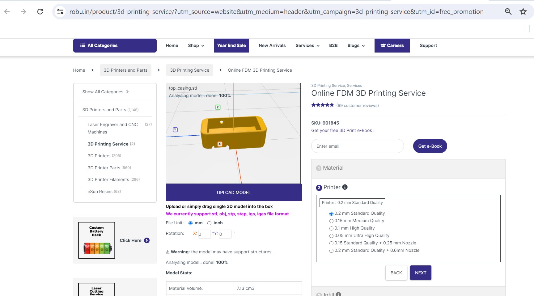
Select in Fill->20%->NEXT
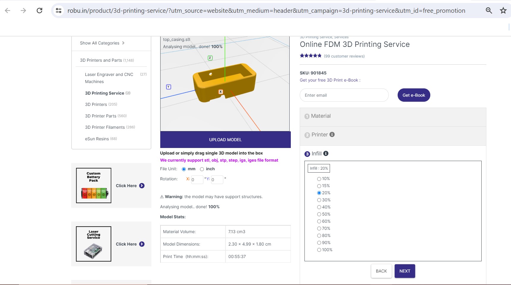
Finalize printing Cost will show -> Select Quantity -> Add to cart
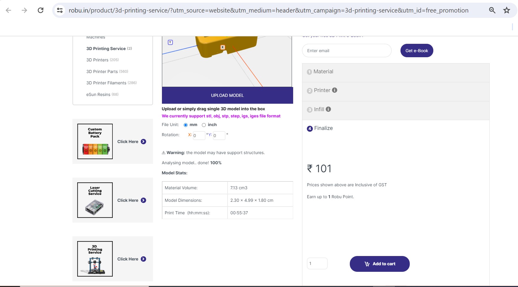
Follow the same process for other STL files
View cart->Apply coupon if you have->verify the material, cost and quantity->Proceed to checkout->make the payment

Hardware interfacing and final test
circuit is fitted in 3d printed case
Place all the components in 3D case, connect them according to circuit diagram with wires
if you need portable device add switch and battery we have added switch and battery in this pulseoxy
Close the 3D case and Switch on the oximeter

Final working of project
we have switched ON the device and placed finger in pulseoxy the sensor read the data and transfer it to controller ,controller process it and display it on OLED display which is connected to controller.
controller connects to Wi-Fi and sends data to Arduino cloud and Arduino cloud update it on dashboard.

Conclusion
In this way we have completed the Pulseoxy project using SEEED STUDIO XIAO ESP32-C3,MAX30102 and OLED display . Pulseoxy measures and shows Heart rate and SPO2 on OLED display it Automatically connects to your Wi-Fi and shows you real-time Heart rate and SPO2 on Arduino Cloud dashboard As well as on IOT Remote APP.
Watch full tutorial on YouTube :- https://youtu.be/KG3ZActfjWs



Akshay Veturlekar
Friday, July 19, 2024