


 Sell on Robu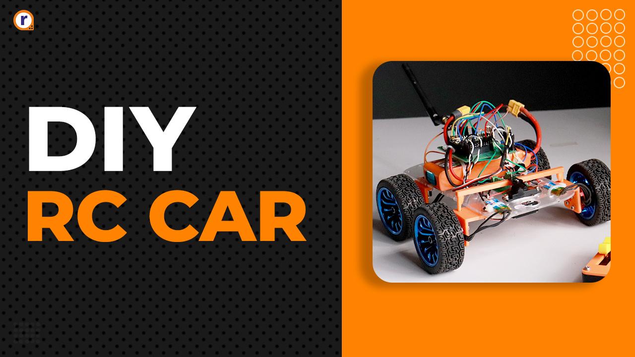


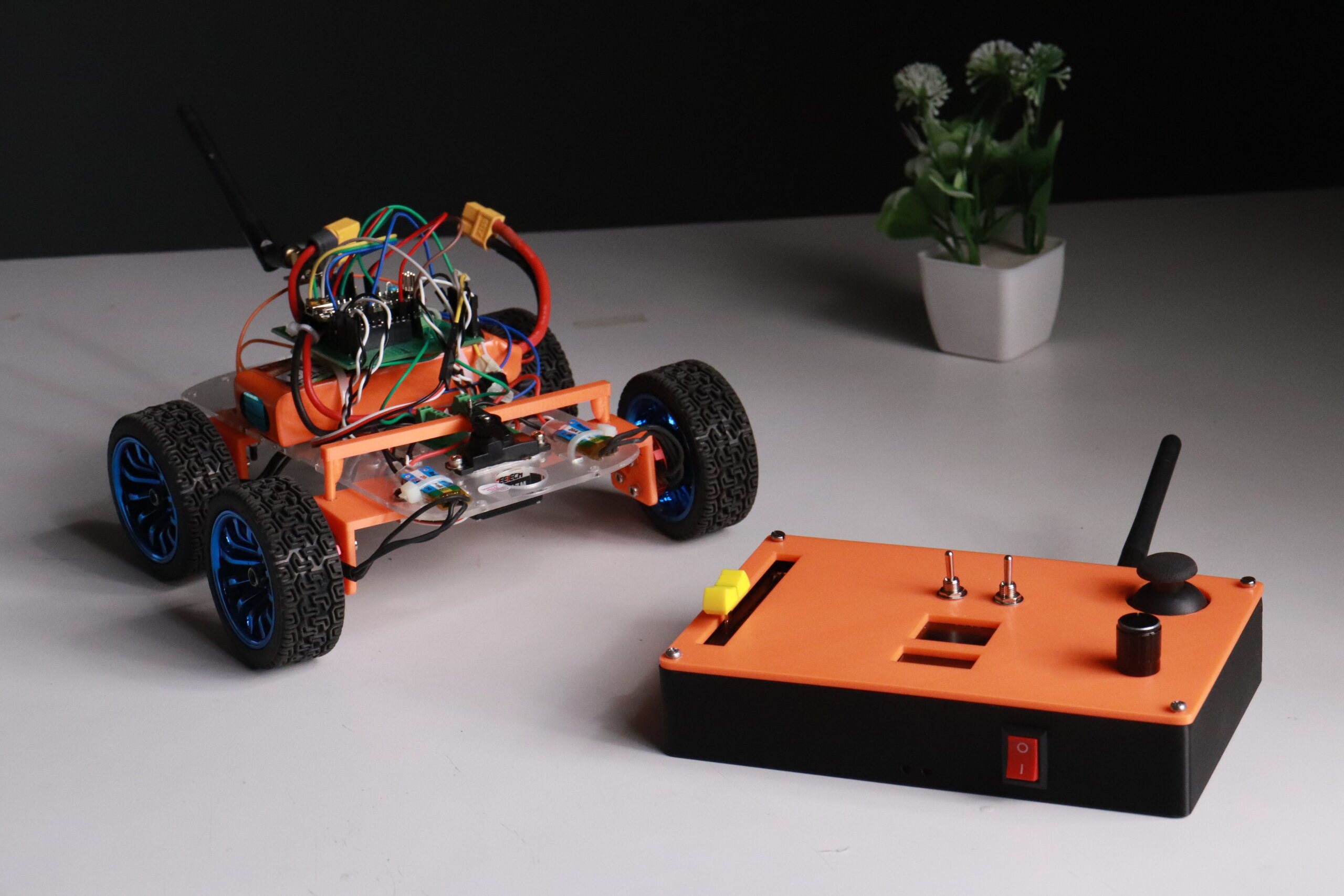
Today, we'll be building a RC Car and show you how to make yourself one. And also control with our previously made RC Remote.
So, further wasting any time. Let's dive right into it.
Table of Contents
What is RC Car ?
Radio-controlled cars, or RC cars for short, are miniature model cars, vans, buses, trucks or buggies that can be controlled from a distance using a specialized transmitter or remote.
RC is used interchangeably for both "radio control" and "remote control", they both mean the same.
And as for the brains of the car, we'll be using Arduino nano.
What is Arduino Nano ?
Arduino Nano is a small, complete, and breadboard-friendly board based on the ATmega328. It has more or less the same functionality of the Arduino Duemilanove, but in a different package.
It lacks only a DC power jack, and works with a Mini-B USB cable instead of a standard USB B.
Some of the key features are -
- ATmega328
- 2kB RAM
- 7-12V Supported
- 1× UART, 1× I2C controllers, 1x SPI, 6× PWM channels
Hardware Requirements of this Project -
- Arduino Nano
- Ready to SKY BLDC Motor
- Ready to SKY 20A ESC
- nrf24L01+PA+LNA with adapter board
- Transparent Robot Smart Car Chassis
- 65mm Robot Smart Car 12 Rim Wheel
- Orange OT5316M 7.4V 15kg.cm Metal Gear Digital Servo Motor
- Orange 11.1V 2200mAh 40C 3S Lithium Polymer Battery Pack
- LM2596S DC-DC Buck Converter
- 7 x 9 cm Universal PCB Prototype
- Screw Terminal Block
- Male and female headers
Software Requirements of this Project -
Circuit Diagram and Hardware Interfacing -
Circuit Diagram -
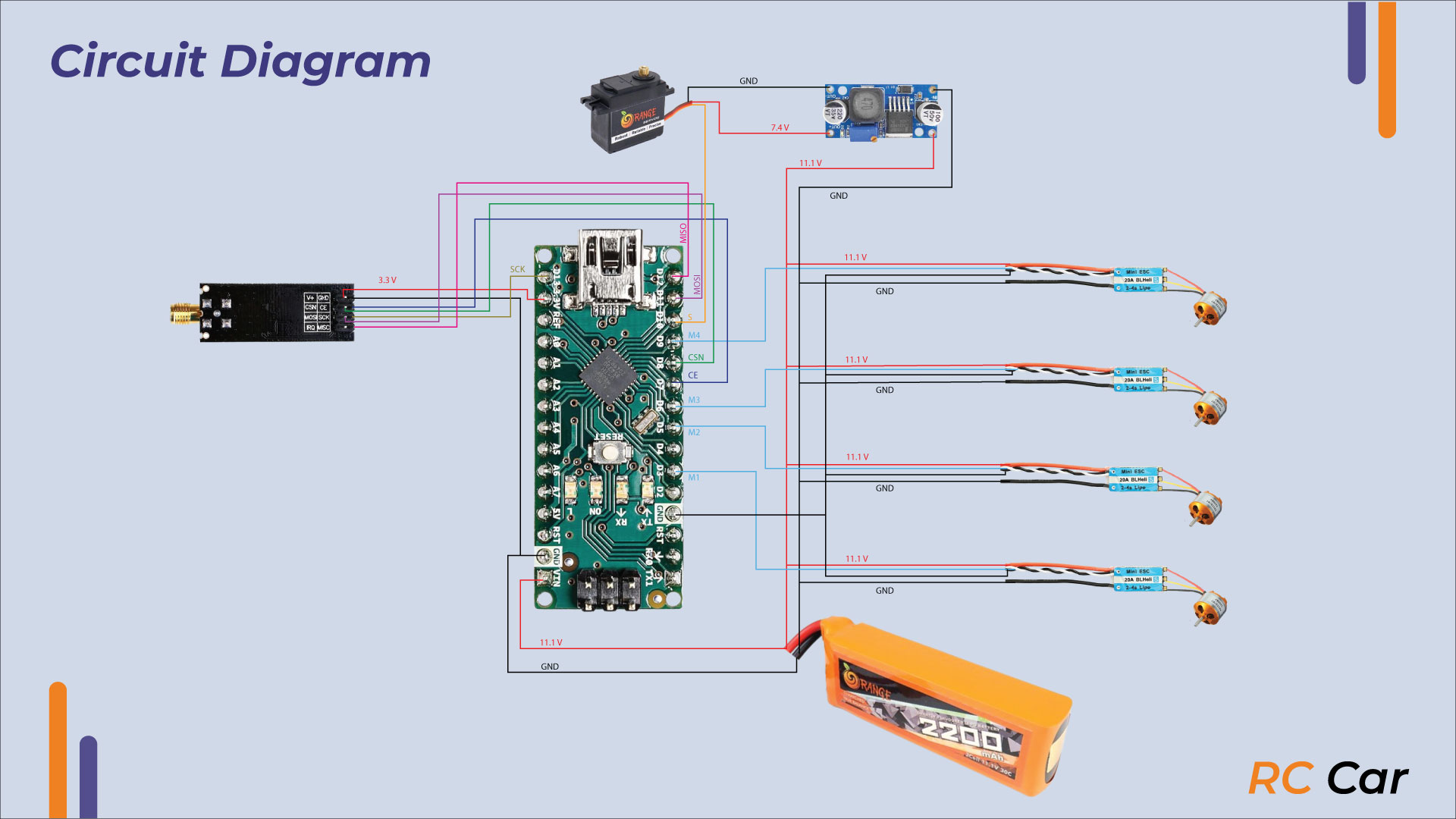
Hardware Interfacing -
Arduino Nano
|
Arduino Nano |
NRF24L01 |
|
7 |
CE |
|
8 |
CSN |
|
SCK |
SCK |
|
MISO |
MISO |
|
MOSI |
MOSI |
|
Arduino Nano |
Motor Signal Wires |
|
3 |
M1 |
|
5 |
M2 |
|
6 |
M3 |
|
9 |
M4 |
|
10 |
Servo Signal |
Coding -
Copy the following code into the IDE. You can make changes to it to fit your needs.
But before testing make sure no one is close by and wheels aren't fitted on the car.
#include <SPI.h>
#include <nRF24L01.h>
#include <RF24.h>
#include <Servo.h>


RF24 radio(7, 8); // CE, CSN
const byte addresses[][6] = {"00001", "00002"};

struct pack{
  int spot=0, x=0, y=0, jsw=1, trim=0;
};

struct drone{
  int batt;
};

pack data;
drone stat;

Servo m1,m2,m3,m4, stere;

void setup() {
  Serial.begin(9600);

  m1.attach(3, 1000, 2000);
  m2.attach(5, 1000, 2000);
  m3.attach(6, 1000, 2000);
  m4.attach(9, 1000, 2000);
  stere.attach(10);

  pinMode(A0, INPUT);
  pinMode(A2, OUTPUT);

  radio.begin();
  radio.setRetries(15, 15);
  radio.openWritingPipe(addresses[0]); // 00001
  radio.openReadingPipe(1, addresses[1]); // 00002
  radio.setPALevel(RF24_PA_MIN);

  delay(100);

}

int throttle=0, turn=0;

void loop() {

  delay(25);
  radio.startListening();

  if (radio.available()) {
    radio.read(&data, sizeof(data));

    if(data.y < 480){
      throttle = map(data.spot, 0, 1023, 1300, 1350);
    }

    else if(data.y > 520){
      throttle = map(data.spot, 0, 1023, 1300, 1200);
    }

    else{
      throttle = 1300;
    }

    turn = map(data.x, 0, 1023, 95, 45);

    if(data.jsw == 0){
      digitalWrite(A2, HIGH);
    }

    else{
      digitalWrite(A2, LOW);
    }


    m1.writeMicroseconds( throttle );
    m2.writeMicroseconds( throttle );
    m3.writeMicroseconds( throttle );
    m4.writeMicroseconds( throttle );
    stere.write(turn);


    serial_debug();


    // delay(25);
    // radio.stopListening();
    // stat.batt = 50 ;  //map(analogRead(A0), 836, 1023, 0, 100); // 826 low batt
    // radio.write(&stat, sizeof(stat));
  }

}


void serial_debug(){
  Serial.print(data.spot);
  Serial.print("  ");
  Serial.print(data.x);
  Serial.print("  ");
  Serial.print(data.y);
  Serial.print("  ");
  Serial.print(data.jsw);
  Serial.print("  ");
  Serial.print(data.trim);
  Serial.println("  ");
}
Working of Project -
Basically, using the nrf24L01 modules to control the car remotely. And the instructions given to the car are simple. It only contains how much throttle, and in which direction to move.
To control the the steering servo, we've used a buck converter to convert 11.1V to 7.4 Volt which is needed by the servo to function correctly.
Conclusion -
If there's no major error till this point. Then congratulation, you've successfully made a Remote Controlled Car as your RC projects.
- For more such Arduino and Raspberry Pi Pico based projects,
check out our Arduino Playlist and Raspberry Pi Pico Playlist
- And for other more interesting projects, check our main YouTube Channel



Leave a Comment Your email address will not be published. Required fields are marked*