


This is a simple but very useful module which uses a potential divider to reduce an input voltage by a factor of 5. The Voltage Detection Sensor Module 25V allows you to use the analog input of a microcontroller to monitor voltages much higher than it capable of sensing.
For example with a 0-5V analog input range, you are able to measure a voltage up to 25V. This voltage sensor module also includes convenient screw terminals for easy and secure connection of a wire.
This module is based on the principle of resistive voltage divider design, can make the red terminal connector input voltage to 5 times smaller. Arduino analog input voltages up to 5 v, the voltage detection module input voltage not greater than 5Vx5=25V (if using 3.3V systems, input voltage not greater than 3.3Vx5=16.5V).
Arduino AVR chips have 10-bit AD, so this module simulates a resolution of 0.00489V (5V/1023), so the minimum voltage of input voltage detection module is 0.00489Vx5=0.02445V.
Note:
Keep in mind, you are restricted to voltages that are less than 25 volts. More than that and you will exceed the voltage limit of your Arduino input.
Connection Diagram

Features :
- Output Interface: “+ ” connected 5/3.3V, “-” connected GND, “s” connected Arduino AD pins
- DC input interface: red terminal positive with VCC, negative with GND
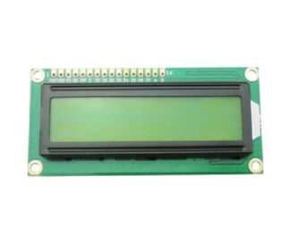
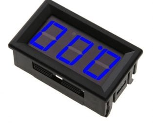
- You can also use the IICLCD1602 LCD to display voltage.
- By 3P connector, connect this module with the expansion of board Arduino, not only makes it easier for you to detect voltage battery.
Package Includes :
1×Voltage Detection Sensor Module


jitenadvanistudy (verified owner) –
Good Quality
jitenadvanistudy –
MrNams (verified owner) –
I have not tested it,but packaging and handling was best
MrNams –
sibap865 (verified owner) –
Worked excellent for me
sibap865 –
vizhigreen (verified owner) –
Tested Ok. Very useful for my Battery Monitoring system
vizhigreen –
Akshay KG (verified owner) –
Good product and working great in my project
Akshay KG –
Yugal kishor (verified owner) –
Perfectly working for my project
Yugal kishor –
komala –
nice
komala –