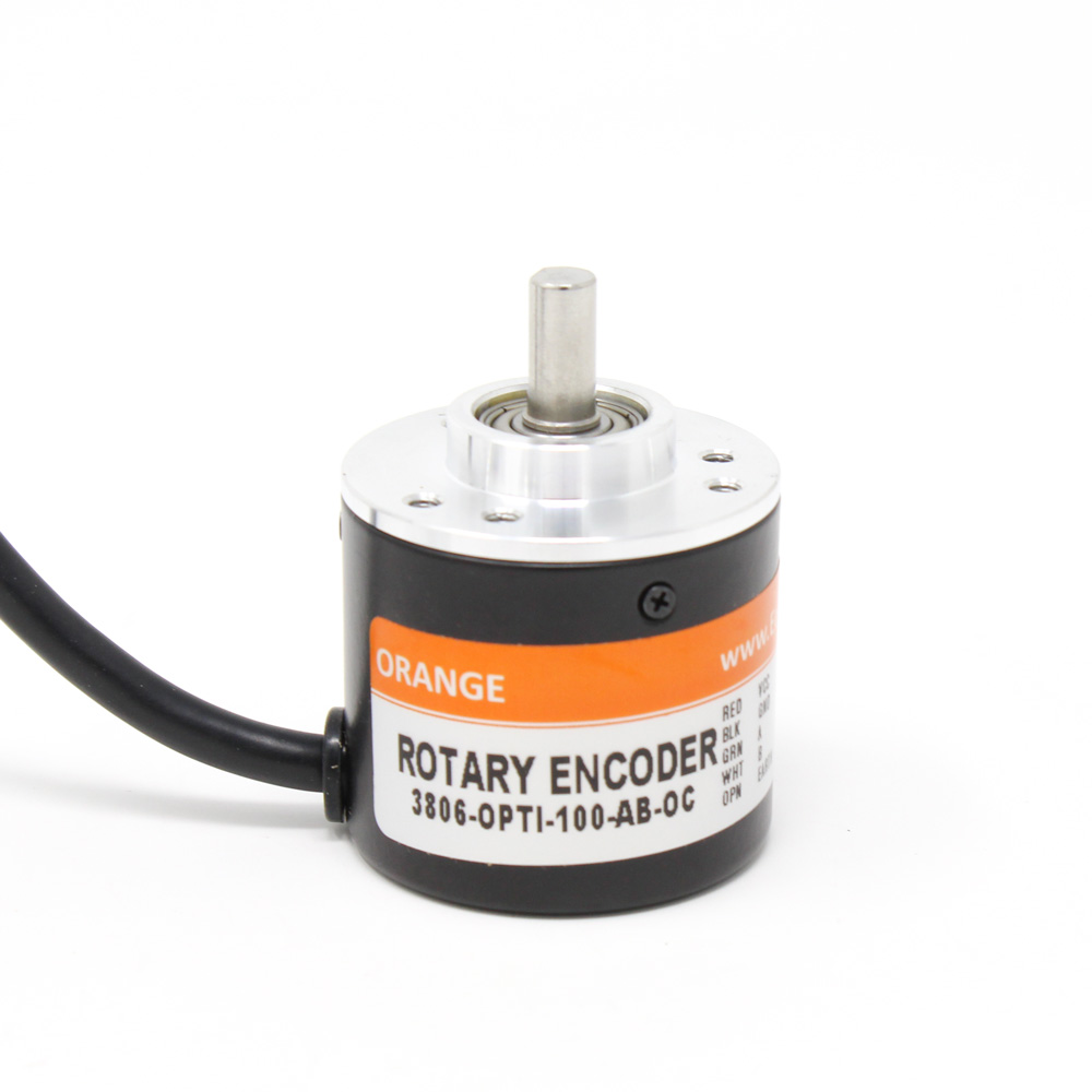
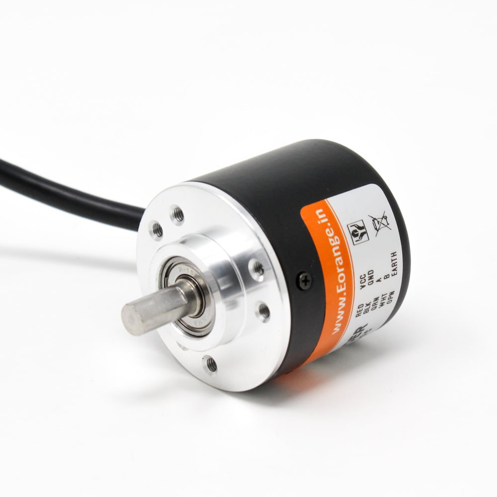
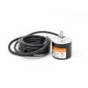
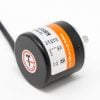
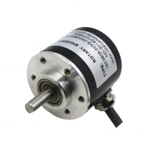
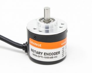
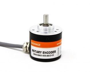
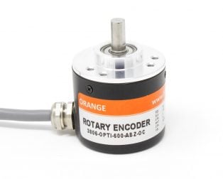
If you want to build a project where the machine can control the speed of the conveyer belt as well as the direction of movement, a rotary encoder is a must-have component. Keeping this in mind, Robu.in is introducing the brand new orange 100 PPR 2-Phase Incremental Optical Rotary Encoder at a competitive price.
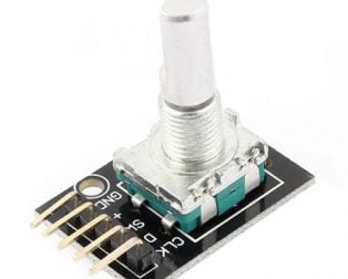
A rotary encoder is a type of position sensor which is used for determining the angular position of a rotating shaft. It generates an electrical signal, either analog or digital, according to the rotational movement.
This is a 100PPR resolution optical encoder with quadrature outputs for increment counting. It will give 400 transitions per rotation between outputs A and B. A quadrature decoder is required to convert the pulses to an up count. The Encoder is built to Industrial grade.
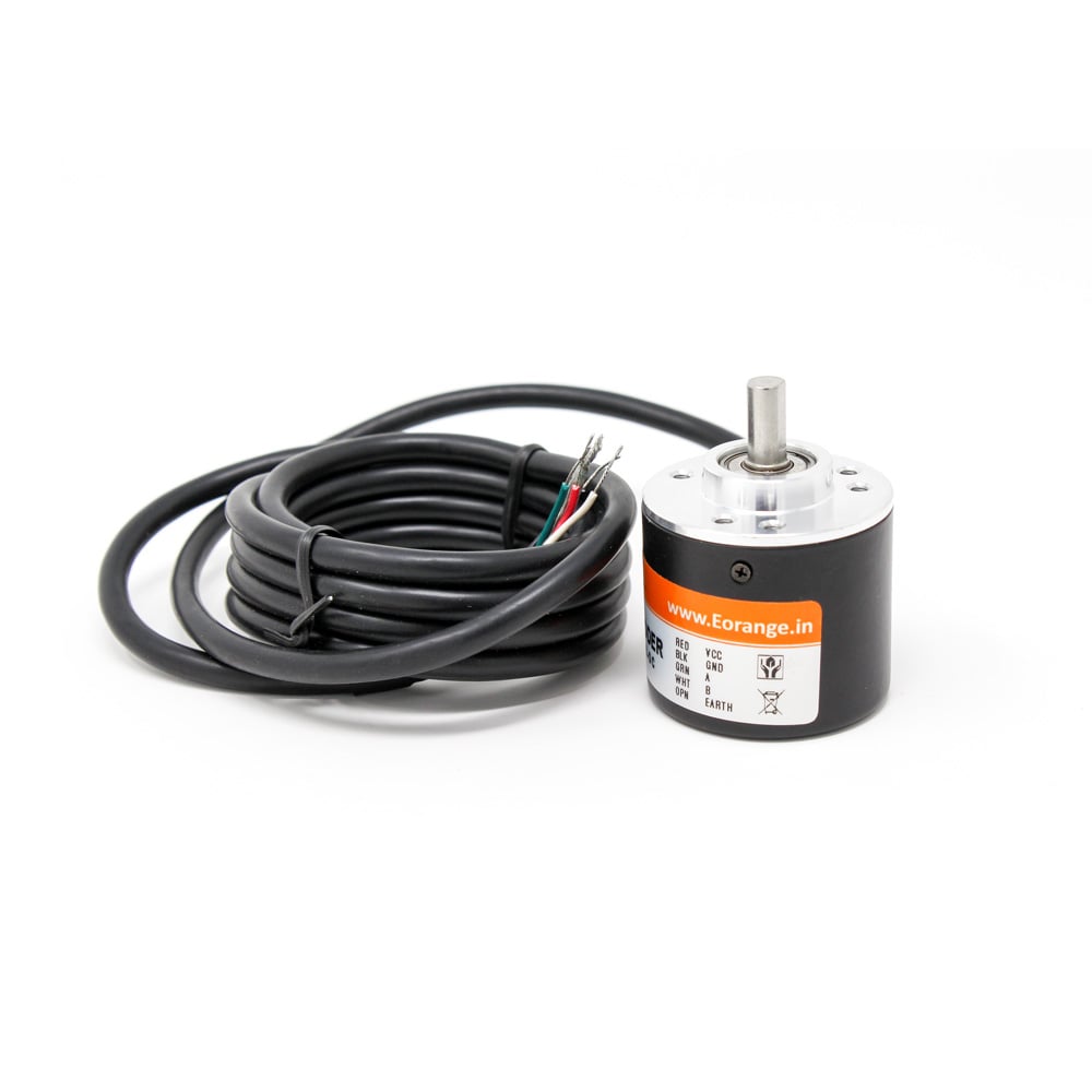
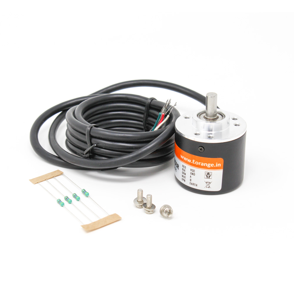
The Encoder comes with a Standard 1.5 m cable length which can be extended with extra cable if needed.
Consider Adding Pull up resistor to both the A and B phases of the encoder output to avoid the effect of interference in output and get the precise logical output value from the encoder Also adding a pull-up resistor to all phase output lines protects the open collector output-triode from damage due to direct Vcc supply short circuit.
Note: A sample tutorial code has been given in the Description Section.
Power and Input Terminal Assignments:
| Terminal Name | Wire Color | Description |
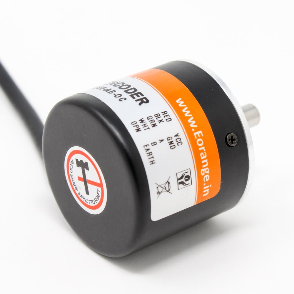
| Phase A | White | Quadrature encoded output A |
| Phase B | Green | Quadrature encoded output B |
| VCC | Red | VCC should be connected to +ve 5V of supply |
| GND | Black | The ground should be connected to negative the supply |
| Shield | Golden | The shield should be connected to GND |
Shielding is important. At a minimum, the cable should be protected either by a foil jacket with a drain wire or by a braided-wire shield that is grounded. For very sensitive applications or high-EMI environments, foil jacketed wires in combination with an overall braided-wire shield around the cable should be used to avoid interference and precise encoder output.
To Explore More Rotary Encoders, Click here
Features :
- High cost-efficient advantages.
- Incremental rotary encoder internal adopts ASIC devices
- High reliability, long life
- Anti-jamming performance
- Small size, lightweight, compact structure
- Easy installation
- Stainless steel shaft, High resolution, High quality, line interface with waterproof protection
Useful Link:
https://electricdiylab.com/how-to-connect-optical-rotary-encoder-with-arduino/
Tutorial Code:
//these pins can not be changed 2/3 are special pins
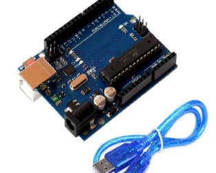
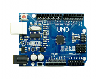
int encoderPin1 = 2;
int encoderPin2 = 3;

volatile int lastEncoded = 0;
volatile long encoderValue = 0;

long lastencoderValue = 0;

int lastMSB = 0;
int lastLSB = 0;

void setup() {
  Serial.begin (9600);

  pinMode(encoderPin1, INPUT);
  pinMode(encoderPin2, INPUT);

  digitalWrite(encoderPin1, HIGH); //turn pullup resistor on
  digitalWrite(encoderPin2, HIGH); //turn pullup resistor on

  //call updateEncoder() when any high/low changed seen
  //on interrupt 0 (pin 2), or interrupt 1 (pin 3)
  attachInterrupt(0, updateEncoder, CHANGE);
  attachInterrupt(1, updateEncoder, CHANGE);

}

void loop(){
  //Do stuff here

  Serial.println(encoderValue);
  delay(1000); //just here to slow down the output, and show it will work  even during a delay
}


void updateEncoder(){
  int MSB = digitalRead(encoderPin1); //MSB = most significant bit
  int LSB = digitalRead(encoderPin2); //LSB = least significant bit

  int encoded = (MSB << 1) |LSB; //converting the 2 pin value to single number
  int sum  = (lastEncoded << 2) | encoded; //adding it to the previous encoded value

  if(sum == 0b1101 || sum == 0b0100 || sum == 0b0010 || sum == 0b1011) encoderValue ++;
  if(sum == 0b1110 || sum == 0b0111 || sum == 0b0001 || sum == 0b1000) encoderValue --;

  lastEncoded = encoded; //store this value for next time
}
Package Includes :
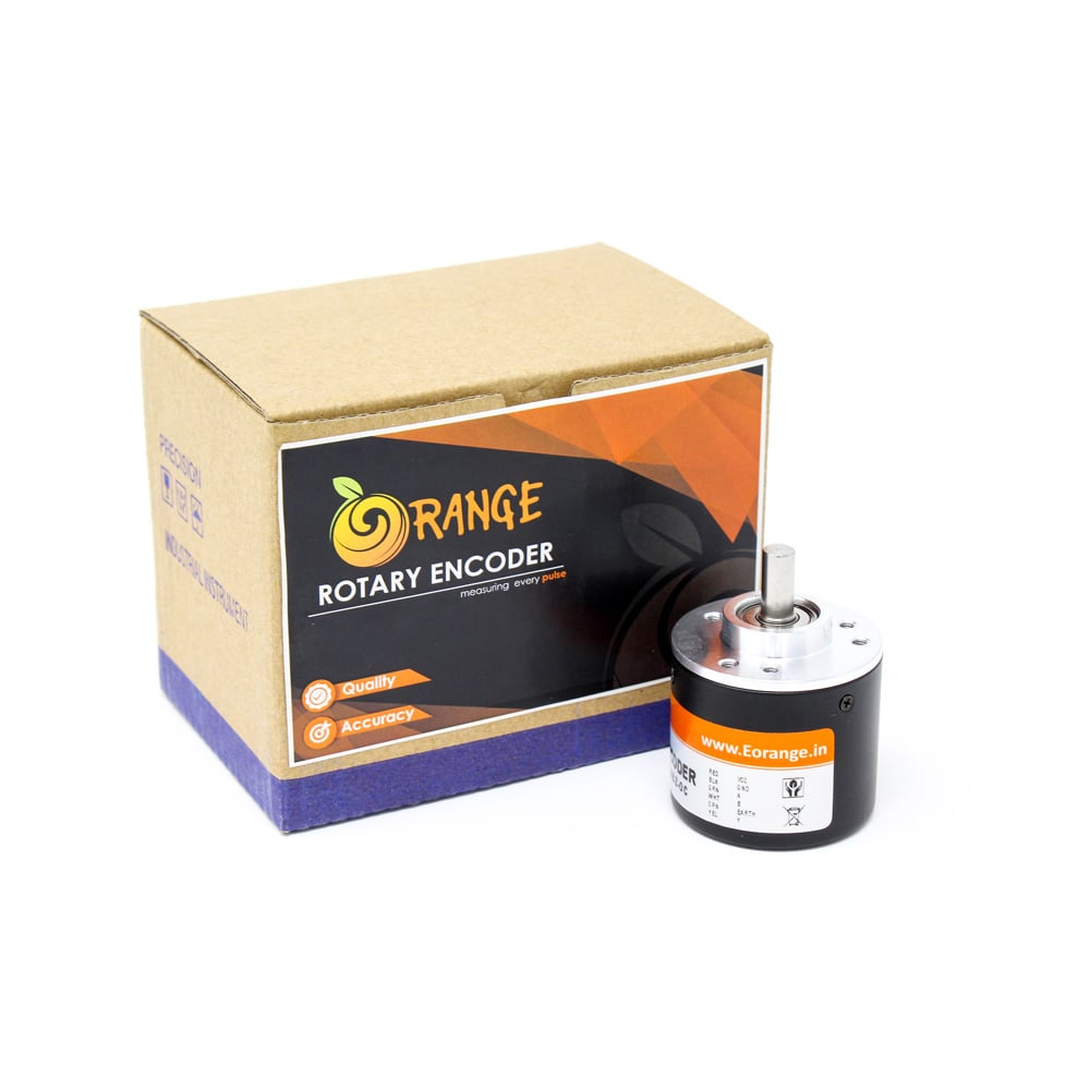
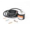
1 x Orange 100 PPR 2-Phase Incremental Optical Rotary Encoder
4 x 4.7KΩ Resistors for pull-ups
1 x Mounting Screw Set


vipin.aniyan (verified owner) –
Very good product
vipin.aniyan –
mil_121 (verified owner) –
good product.
mil_121 –
Nikhilkarthik (verified owner) –
Sir i have a problem in coding, You have not cleared the coding on encoded pin MSB and LSB. The problems on codings should be verified and the encoder is perfect. Im happy with the product
Nikhilkarthik –